Open Nav


The Electronics Manufacturing industry operates under a complex framework of standards, guidelines, and specifications that define what constitutes an acceptable printed circuit board. Without these standards, chaos would reign: every manufacturer would define quality differently, every designer would use incompatible terminology, and every buyer would have no reliable basis for comparing quotations or evaluating compliance. The Institute for Printed Circuits, universally known as IPC, has spent more than six decades developing and maintaining the standards that bring order to this complexity. For engineers working with industrial PCB Fabrication, understanding the key Ipc Standards is not optional professional development. It is foundational knowledge that affects every design decision, every supplier evaluation, and every quality conversation that happens throughout a product's lifecycle.
This article provides a practical guide to the Ipc Standards most relevant to industrial PCB Fabrication. Rather than attempting exhaustive coverage of every standard in IPC's extensive catalog, it focuses on the standards that appear most frequently in engineering practice, explaining what each standard covers, why it matters, and how to use it effectively in your daily work.
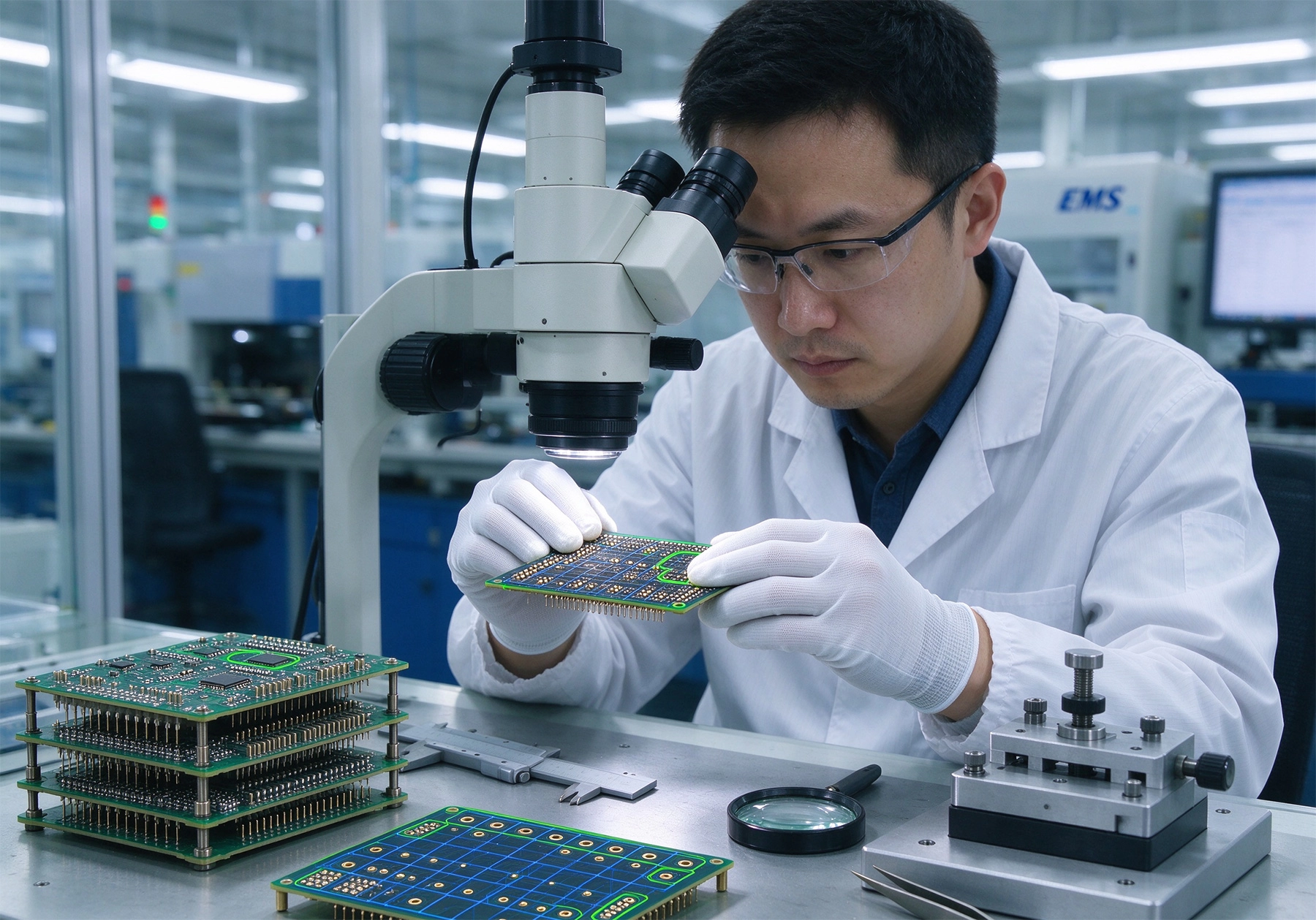
IPC was founded in 1957 as the Institute for Printed Circuits, initially focused on the emerging technology of printed circuit boards that was transforming Electronics Assembly. Over the decades, the organization expanded its scope to encompass the entire Electronics Manufacturing supply chain, changing its full name to the Association Connecting Electronics Industries while retaining the IPC abbreviation that everyone in the industry uses. Today, IPC standards are recognized and referenced globally, forming the common language that enables designers, manufacturers, and customers to communicate precisely about quality requirements, test methods, and performance criteria.
The value of IPC standards extends beyond their technical content. They represent the collective experience of thousands of industry experts who have contributed their knowledge to create documents that reflect real-world manufacturing experience. When you specify Ipc Class 3 requirements, you are not just stating a quality level. You are invoking a comprehensive framework of design guidelines, workmanship criteria, test methods, and acceptance conditions that have been refined over decades of industrial practice. This framework provides a level playing field where buyers can compare quotations on equal terms and manufacturers can demonstrate compliance through objective criteria rather than subjective assertions.
IPC standards are living documents that are updated periodically to reflect advances in technology, changes in manufacturing practice, and lessons learned from field experience. Understanding which version of a standard applies to your requirements matters, because requirements can change between revisions. When specifying IPC compliance, always reference the specific revision you require and confirm that your supplier can meet that revision.
IPC-2221 is the foundational design standard that establishes the fundamental requirements for printed board design across all categories of electronics assemblies. It serves as the parent document from which more specific design standards are derived, covering everything from substrate selection and layer Stack-up Design to Thermal Management and environmental considerations. Every engineer working with Pcb Design should have a working familiarity with IPC-2221, because it establishes the baseline requirements that apply regardless of the specific application or quality level.
The standard organizes design requirements by the three product performance classes originally defined in IPC-2221 and maintained across the IPC standards family. Class 1 covers general electronic products where the primary requirement is function of the completed assembly. Class 2 covers dedicated service electronic products that require extended life and uninterrupted performance but where service is not necessarily required. Class 3 covers high-performance electronic products where continued performance or performance on demand is critical, and downtime is unacceptable. Understanding these class definitions is essential for specifying the appropriate quality level for your product.
Within IPC-2221, engineers will find design rules for trace width and spacing, clearance and creepage distances, via sizing and placement, pad design, and many other fundamental design parameters. These rules are not arbitrary. They represent the minimum requirements that experience has shown are necessary for reliable board fabrication and assembly. Deviating from these rules is possible when justified, but doing so without understanding the basis for the rule often leads to manufacturing problems or field failures.
While IPC-2221 tells designers what to do, Ipc-a-600 tells inspectors what to look for. This standard defines the acceptability criteria for printed boards, describing what constitutes a defect versus acceptable condition for each observable characteristic of a bare PCB. It is the primary reference for incoming inspection of bare boards and for resolving disputes between buyers and manufacturers about whether a board meets quality requirements.
Ipc-a-600 organizes acceptability criteria into three categories corresponding to the three product classes. Acceptable conditions for Class 1 are the most lenient, accepting defects that would not affect basic function. Class 2 criteria are more stringent, reflecting the expectation of extended service life. Class 3 criteria are the most demanding, appropriate for high-reliability applications where any defect that could affect continued performance is unacceptable. The standard provides photographic examples and written descriptions that make the distinction between acceptability levels clear and actionable.
The standard covers a comprehensive range of board characteristics including surface conditions, conductor criteria, Solder Mask quality, via integrity, hole size and shape, and many other parameters. For engineers who do not perform inspection themselves, IPC-A-600 provides valuable insight into what manufacturers are checking and what quality levels are achievable in production. Understanding these criteria helps designers set realistic quality expectations and avoid specifying requirements that are unnecessarily stringent for the actual application needs.
Ipc-6012 is the workhorse standard for rigid printed board qualification and performance requirements in industrial applications. While IPC-A-600 focuses on acceptability criteria for individual boards, Ipc-6012 establishes the requirements for qualifying a manufacturer to produce boards to a specific performance level and defines the performance requirements those boards must meet. In practice, most procurement specifications for industrial PCBs reference IPC-6012 as the governing standard.
The qualification requirements in IPC-6012 define what testing a manufacturer must perform and pass to demonstrate they can produce boards meeting the standard. This includes testing of electrical characteristics, mechanical properties, thermal performance, and environmental resistance. The qualification testing is typically performed once when initially qualifying a manufacturer and may be repeated periodically to verify continued compliance or when significant process changes occur.
Performance requirements in IPC-6012 cover the full range of board characteristics including conductor width and spacing tolerances, dielectric thickness and uniformity, via annular ring dimensions, plating requirements, and many more. The standard specifies different performance levels for each product class, with Class 3 requirements being the most demanding. When you specify IPC-6012 Class 3, you are specifying a comprehensive set of requirements that covers virtually every aspect of board construction and performance.
While IPC-6012 covers bare boards, IPC-A-610 covers the assembled PCB, defining acceptability criteria for the components, solder joints, and assembly processes that make up a completed Electronic Assembly. This is one of the most widely referenced standards in the electronics manufacturing industry, used by manufacturers, quality inspectors, and procurement professionals to define and verify assembly quality. For engineers involved in Pcb Assembly, whether as designers, quality professionals, or program managers, IPC-A-610 is essential reading.
IPC-A-610 organizes requirements by the process that created the feature being inspected, which makes it intuitive to use in production environments. The standard covers component placement, through-hole technology, surface mount technology, and other assembly processes, with specific acceptability criteria for each. Like IPC-A-600, it defines three acceptance levels corresponding to the product classes, with different criteria for each level.
Beyond basic acceptability criteria, IPC-A-610 provides valuable guidance on process control and Defect Prevention. The standard emphasizes that inspection alone cannot achieve quality. Instead, quality comes from well-controlled processes that produce acceptable product consistently. This philosophy has influenced the entire electronics manufacturing industry, shifting focus from inspection-based Quality Control to process-based quality management.
No manufacturing process produces perfect boards every time, and some level of rework and repair is inevitable in electronics manufacturing. IPC-7711 and IPC-7721 provide the standardized procedures for performing rework and repair on electronic assemblies and printed boards respectively. These standards define the methods, materials, and workmanship criteria that ensure rework and repair activities do not compromise the reliability of the finished product.
IPC-7711 covers rework and repair of electronic assemblies including component removal and replacement, trace repair, pad repair, and through-hole repair. The standard provides detailed procedures with illustrations that allow trained technicians to perform complex repairs consistently. It also defines limitations on what can and cannot be repaired, preventing attempts to repair conditions that would not benefit from rework.
IPC-7721 specifically addresses the repair and modification of printed boards and electronic assemblies, covering topics like conductor repair, base material repair, plated hole repair, and board modification. These procedures are essential for maintaining board functionality when defects are discovered or when design changes require board modifications. Using proper repair procedures from IPC standards ensures that repaired boards meet the same reliability requirements as original production boards.
IPC-J-STD-001 is the definitive standard for soldered electrical and electronic assemblies, establishing the materials, methods, and verification criteria for producing high-quality solder joints. While IPC-A-610 defines what acceptability looks like, J-STD-001 defines how to achieve that quality through proper process control. This standard is particularly important for manufacturers seeking to implement rigorous quality systems, because it provides the detailed process requirements that complement the visual acceptance criteria in IPC-A-610.
The standard covers all aspects of the soldering process including flux selection, solder alloy requirements, process temperature profiles, equipment verification, and workmanship criteria. It establishes training and certification requirements for operators performing soldering operations, recognizing that proper technique is essential for consistent quality. The operator certification requirements in J-STD-001 have become an industry benchmark that many companies use as a basis for their own training programs.
J-STD-001 defines three inspection levels corresponding to the product classes, with Level 3 being the most stringent for high-reliability applications. The standard also includes supplementary requirements for specific applications like military, aerospace, and medical devices that go beyond the basic requirements. Understanding J-STD-001 helps engineers specify soldering requirements precisely and evaluate whether potential assembly suppliers have the process controls needed to meet those requirements.
IPC-4101 is the comprehensive specification for base materials used in rigid and multilayer printed boards, covering the full range of laminates, prepregs, and metal-clad materials used in Pcb Fabrication. While many engineers interact with this standard indirectly through material datasheets that reference IPC-4101 specifications, understanding the standard directly helps engineers make informed Material Selection decisions and specify material requirements precisely.
The standard classifies base materials by their performance characteristics including Tg (Glass Transition Temperature),Td (decomposition temperature), Dielectric Constant, dissipation factor, and Thermal Conductivity. Each characteristic is specified at defined test conditions and acceptance criteria. Materials that meet IPC-4101 specifications have demonstrated consistent performance across these parameters, providing confidence that they will perform predictably in production and in service.
For engineers specifying materials, IPC-4101 provides the vocabulary for describing requirements precisely. Rather than specifying a generic material like FR4, which can vary significantly between manufacturers and product lines, specifying IPC-4101 slash codes that define the specific characteristics required ensures consistent material performance regardless of the specific manufacturer or product used. This approach simplifies material sourcing and reduces the risk of unexpected performance variations.
IPC-2581 defines a standardized data format for transferring manufacturing information between designers and manufacturers. This standard addresses a persistent problem in electronics manufacturing: the information needed to produce a Pcb Assembly is often spread across multiple file formats and documents, creating opportunities for miscommunication and error. IPC-2581 provides a unified format that includes all the information needed for Pcb Fabrication and assembly in a single, complete data package.
The standard includes Gerber files, drill data, component placement data, bill of materials, test requirements, and many other elements needed for manufacturing. By standardizing this information in a single format, IPC-2581 reduces the errors that occur when multiple files must be reconciled and ensures that no critical information is omitted from the manufacturing data package.
While adoption of IPC-2581 has been slower than its technical merit would suggest, driven partly by the inertia of existing CAD-to-manufacturing workflows, the standard is increasingly important as the industry moves toward more automated and integrated manufacturing systems. Engineers who understand IPC-2581 are better positioned to participate in conversations about manufacturing data exchange and to take advantage of the efficiency improvements that standardized data transfer enables.
For aerospace applications, IPC-9592 provides specialized requirements that supplement the general-purpose IPC standards with additional requirements specific to the aerospace environment. This standard recognizes that aerospace applications impose demands on Pcb Performance that go beyond what general-purpose standards address, including resistance to Thermal Cycling, vibration, humidity, and other environmental stressors encountered in flight operations.
The standard covers design requirements, Material Selection, manufacturing controls, and qualification testing specific to aerospace applications. It references other IPC standards but adds supplementary requirements where the general standards are insufficient for aerospace reliability expectations. Engineers working on aerospace electronics should be familiar with IPC-9592 and understand how it supplements the baseline IPC requirements they would otherwise follow.
Beyond IPC-9592, aerospace applications often involve additional industry-specific standards from organizations like SAE and RTCA that address requirements not covered in IPC documents. Understanding the complete regulatory landscape for aerospace electronics, of which IPC-9592 is a key component, is essential for engineers working in this demanding sector.
Knowing that IPC standards exist and understanding their content are different skills. Using IPC standards effectively in practice requires knowing how to reference them in procurement documents, how to verify compliance, and how to resolve disputes when disagreements arise about whether requirements are met.
When specifying IPC requirements in purchase orders or supplier agreements, be specific about which standard, which revision, and which class or level you require. Vague references to IPC compliance invite ambiguity and dispute. A precise specification like IPC-6012 Rev D Class 3 provides a clear, unambiguous requirement that both parties can evaluate and verify. Including the specific standard reference also ensures that any party to the agreement can access the standard document and understand exactly what is required.
For quality-critical applications, consider requiring manufacturers to provide IPC certification or qualification documentation as part of your supplier qualification process. IPC offers training and certification programs that verify individuals have demonstrated knowledge of relevant standards, and manufacturer participation in these programs provides additional confidence in their understanding of and commitment to IPC requirements.
When disputes arise about whether boards or assemblies meet IPC requirements, the standards themselves provide the framework for resolution. Both parties should review the relevant standard sections together, agree on what criteria apply, and evaluate the specific boards in question against those criteria. If agreement cannot be reached, escalation to independent inspection or third-party mediation may be necessary, but the IPC standards provide the common reference point that makes these resolution processes possible.
IPC standards are periodically revised to incorporate new technology, address identified deficiencies, and reflect lessons learned from industry experience. Staying current with relevant revisions ensures that your specifications reflect the latest industry consensus and that you are not inadvertently requiring outdated practices or accepting obsolete test methods.
IPC provides notification services that alert subscribers when standards are updated, and most standards organizations offer subscription packages that include access to all current revisions. Investing in these subscription services is worthwhile for organizations with significant Pcb Manufacturing activity, because the cost is small compared to the problems that can arise from specifying outdated requirements.
When new revisions are released, take time to understand what has changed and whether those changes affect your current specifications. Some revisions introduce new requirements that may require process changes or equipment upgrades. Others clarify ambiguous language that may affect how existing requirements are interpreted. Understanding the changes allows you to update your specifications appropriately and to plan for any implementation requirements the new revision introduces.
IPC standards form the common language of the electronics manufacturing industry, providing the framework of definitions, requirements, test methods, and acceptance criteria that enable designers, manufacturers, and customers to communicate precisely about quality. For engineers working with Industrial Pcb fabrication, familiarity with the key standards covered in this article is foundational knowledge that affects every aspect of the job from initial design through final product delivery.
The standards discussed here represent a starting point rather than an exhaustive catalog. IPC publishes many additional standards covering specific topics like Flexible Circuits, high-frequency materials, lead-free manufacturing, and many other specialized areas. As your work touches these areas, additional IPC standards become relevant and worth studying in depth.
The investment in understanding IPC standards pays dividends throughout your career. It enables more precise specifications, more productive conversations with manufacturers, more effective quality management, and more confident decision-making about acceptable quality levels. In an industry where clarity and precision matter enormously, the IPC standards provide the vocabulary and framework that make clarity and precision possible.
Contact us to discuss your requirements and explore how IPC standard knowledge can support your Industrial Pcb fabrication and assembly needs.
Precision Engineering: Tolerances in High-End Industrial PCB FabricationSeptember/03/2026
Predicting Lifespan: Accelerated Life Testing for Industrial PCB ReliabilityAugust/03/2026
The Role of Laser Drilling in High-Precision Industrial PCB FabricationOctober/15/2026
The Impact of Surface Finishes on Industrial PCB Fabrication QualityJuly/16/2026

How to Choose the Right Manufacturer for Industrial PCB FabricationJune/29/2026

Eco-Friendly Practices in Modern Industrial PCB FabricationSeptember/20/2026

Overcoming Common Defects in Industrial PCB FabricationAugust/03/2026
Materials, Methods, and Industry Standards ExplainedMay/27/2026