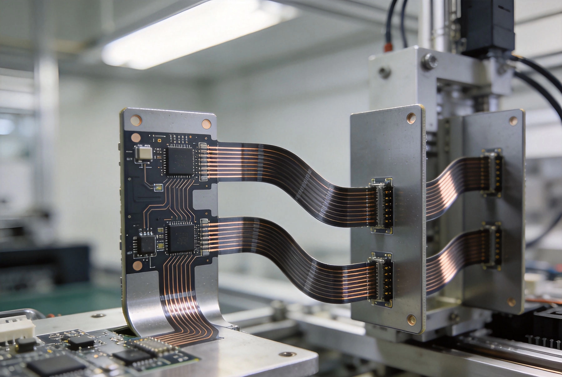
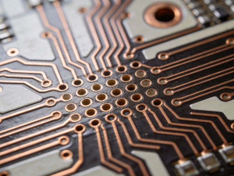
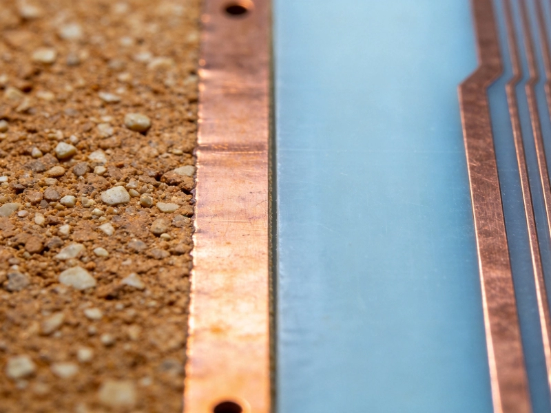
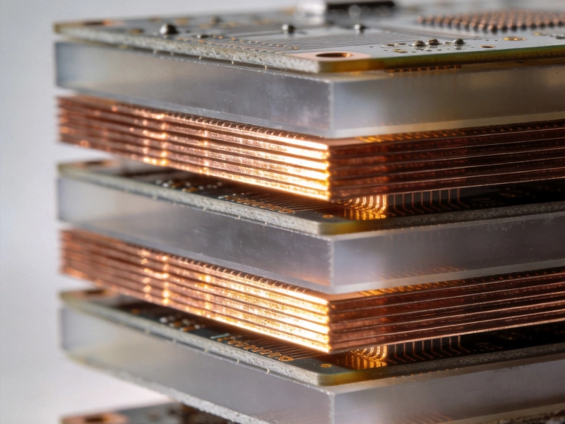
When engineers design complex industrial equipment, they face a persistent challenge: how do you route electrical signals between rigid components that move, rotate, or occupy unconventional geometries? Traditional wiring harnesses add bulk and reliability concerns. Rigid PCBs alone cannot conform to complex enclosures. This is where Rigid-flex Pcb solutions deliver transformative advantages.
Rigid-flex PCBs combine the structural support of rigid boards with the dynamic flexibility of thin-film circuits. The result is a single, integrated assembly that replaces multiple components, simplifies manufacturing, and dramatically improves reliability. For industrial applications where failure is not an option, rigid-flex technology has become the preferred solution.

Understanding Rigid-Flex PCB Technology
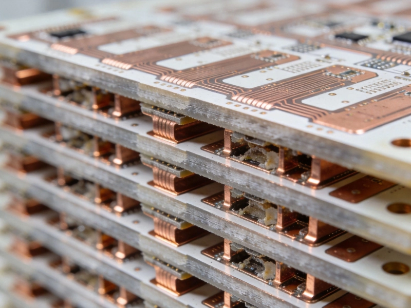
A Rigid-flex Pcb consists of rigid sections—typically made from traditional FR-4 or High-tg Materials—interconnected by flexible sections using polyimide (PI) or polyester (PET) substrates. These hybrid assemblies are designed, fabricated, and assembled as complete units rather than separate components that must be connected during final assembly.
Core Structural Elements
The basic architecture includes:
- Rigid sections: Multi-layer boards with standard construction for component mounting, connectors, and structural support
- Flexible sections: Single, double, or multi-layer Flexible Circuits that bend dynamically or maintain fixed shapes
- Transition zones: Carefully designed areas where rigid sections meet flexible sections, managing stress concentrations
- Bonding layers: Adhesive systems that securely join rigid and flex layers while maintaining flexibility
Manufacturing Complexity
Unlike standard rigid boards or simple Flexible Circuits, rigid-flex PCBs require:
- Sequential Lamination processes that build multiple rigid sections with continuous flex layers
- Specialized drilling and plating for vias that transition between rigid and flexible regions
- Careful Material Selection to match thermal expansion coefficients across the assembly
- Advanced testing to verify both rigid section functionality and flex region durability
This complexity increases manufacturing cost by 30-50% compared to equivalent rigid assemblies, but the total system cost savings often justify the investment.
Key Benefits for Industrial Applications
1. Space and Weight Reduction
Industrial equipment increasingly demands miniaturization without sacrificing functionality. Rigid-flex solutions enable:
- Elimination of connectors: Direct circuit connections remove bulky and failure-prone connector interfaces
- Reduced assembly height: Flat flexible sections replace wire bundles that require routing space
- Compact form factors: Boards can fold to fit irregular enclosures, utilizing space that rigid boards cannot access
- Weight savings: Flexible circuits weigh 60-80% less than equivalent wire harnesses
In aerospace and mobile industrial equipment, every gram matters. The cumulative weight reduction from rigid-flex assemblies can significantly impact fuel efficiency and battery life.
2. Superior Reliability
Rigid-flex PCBs dramatically outperform traditional interconnect methods in demanding environments:
- Eliminated connection points: Fewer solder joints and connectors mean fewer potential failure sites
- Vibration resistance: Flexible sections absorb mechanical stress that would fatigue rigid connections
- Consistent impedance: Controlled Impedance traces maintain Signal Integrity through flex regions
- Material consistency: Single-piece construction eliminates differential expansion issues between joined assemblies
Industrial motor drives, hydraulic controls, and mining equipment routinely achieve 100,000+ hour operational lifecycles with rigid-flex assemblies that would fail within months using traditional wiring.
3. Design Freedom
The ability to fold, bend, and wrap rigid-flex assemblies around mechanical structures enables designs impossible with rigid boards alone:
- Three-dimensional routing: Signals navigate around mechanical obstructions without wire management complexity
- Rotating interfaces: Slip rings and rotary joints can be replaced with flexible connections for continuous rotation
- Hinge integration: Laptop-style hinges and access panels maintain electrical continuity through flex sections
- Thermal Management: Heat-generating components on rigid sections can be positioned optimally, with flex sections routing signals around thermal zones
4. Simplified Assembly
From an manufacturing perspective, rigid-flex reduces production complexity:
- Reduced part count: One rigid-flex assembly replaces multiple rigid boards, flex cables, and connectors
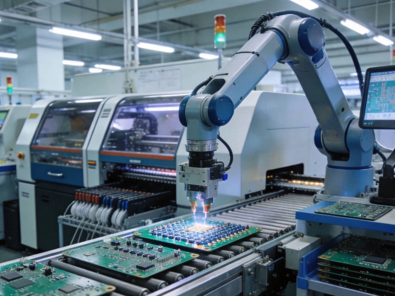
- Automated assembly: Surface mount components on rigid sections can use standard pick-and-place equipment
- Consolidated testing: The complete assembly is tested as one unit before installation
- Field serviceability: Modular rigid sections can be repaired or replaced while maintaining flex connections
Design Considerations for Industrial Rigid-Flex
Material Selection
Material choices significantly impact both performance and cost:
- Polyimide (PI): The industry standard for flex layers—excellent Thermal Resistance (up to 400°C), high flexibility, and proven reliability. More expensive than alternatives.
- PET ( polyester): Lower cost option suitable for static or minimal-flex applications. Temperature limited to ~150°C.
- High-Tg rigid materials: For elevated temperature industrial environments, specify Tg values exceeding 170°C to prevent lamination issues during assembly.
- Adhesive systems: Acrylic adhesives offer cost and processing advantages; epoxy prepregs provide superior thermal performance but require more careful processing.
Flex Region Design Rules
Flexible sections require careful design to ensure long-term reliability:
- Bend Radius: Minimum Bend Radius typically 6-10x the flex layer thickness for dynamic applications; tighter radii acceptable for static formations
- Trace orientation: Route traces perpendicular to bend axes to minimize conductor strain
- Stiffener placement: Add polyimide or FR-4 stiffeners in areas where components must be supported in flex regions
- Coverlayer design: Protective coverlayers should terminate at least 0.5mm from bend edges to prevent cracking
- Anchor and Strain Relief: Include features that transfer flex stress to the rigid sections rather than concentrating it at termination points
Layer Stackup Optimization
The layer count and stackup configuration impact both electrical performance and manufacturing yield:
- Rigid section layer count: Typically 4-12 layers depending on component density and routing complexity
- Flex layer count: Usually 1-4 layers; multi-layer flex increases thickness and reduces flexibility
- Symmetry: Maintain layer symmetry around the neutral axis to prevent warpage during processing
- Ground planes: Include ground planes in flex regions for improved Impedance Control and EMI performance
Applications in Industrial Electronics
Motor Drives and Power Electronics
Industrial motor drives require dense Power Electronics with connections across moving or vibrating interfaces. Rigid-flex PCBs provide:
- Gate driver connections that flex around heat sinks and transformers
- Current sensing circuits routed through physically constrained areas
- Control board connections that survive decades of Thermal Cycling
Industrial Automation and Robotics
Robotic arms and automated guided vehicles (AGVs) place extreme demands on electrical interconnects:
- Continuous rotation capabilities for tool changers and Cable Management
- Vibration resistance for joint-mounted electronics
- Compact form factors enabling integration into actuator housings
- Quick-disconnect capabilities for field serviceability
Heavy Equipment and Mining
Equipment operating in harsh industrial environments benefits from rigid-flex reliability:
- Sealed enclosures with rigid-flex feedthroughs eliminating penetrations
- Operator interface assemblies with integrated displays and controls
- Telescopic boom connections maintaining signals through extension/retraction cycles
Medical and Laboratory Equipment
While not strictly industrial, medical manufacturing equipment shares similar requirements:
- Sterilization-compatible designs using high-temperature materials
- Precision motion control connections for robotic surgery systems
- Diagnostic equipment requiring compact, reliable assemblies
Manufacturing Partner Selection
Essential Capabilities
Not all PCB manufacturers can produce reliable rigid-flex assemblies. Verify your partner offers:
- Sequential Lamination experience: Ask for examples of builds with multiple rigid sections and continuous flex layers
- Flex material handling: Proper storage, handling, and processing of polyimide and other flex materials
- Flex-specific testing: Dynamic Flex Testing, bend cycle verification, and visual inspection of flex regions
- Design support: Experienced engineers who can optimize your Design For Manufacturability
- Quality certifications: ISO 9001 minimum; IATF16949 or industry-specific certifications for critical applications
Questions to Ask Potential Suppliers
Before committing to a manufacturing partner, clarify:
- What is your minimum bend radius for dynamic flex applications?
- How do you handle flex-to-rigid transition stress relief?
- What testing do you perform on flex regions specifically?
- Can you provide flex cycle testing data for similar applications?
- What are your typical yields for rigid-flex assemblies vs. rigid-only?
- Do you offer Design For Manufacturability (DFM) review as part of the quotation process?
Cost Considerations and Value Analysis
When Rigid-Flex Makes Economic Sense
Rigid-flex technology is not always the right choice. Consider rigid-flex when:
- Space or weight constraints make traditional assemblies impractical
- High reliability requirements justify premium pricing
- The application involves dynamic motion or repeated flexing
- Assembly complexity with multiple boards and connectors is consuming manufacturing time
- Field failures from connector or wiring issues are costly to address
Total Cost of Ownership Analysis
Compare rigid-flex against traditional alternatives by evaluating:
- Component cost differential: Rigid-flex assemblies typically cost 30-50% more than equivalent rigid boards
- Assembly labor savings: Single-piece installation vs. multiple boards, connectors, and cable harnesses
- Testing efficiency: Consolidated testing reduces inspection time and improves defect detection
- Field failure costs: Weight connector and wire harness failure rates against rigid-flex reliability data
- Rework and repair: Evaluate the serviceability of rigid-flex vs. integrated alternatives
In high-volume production, the initial rigid-flex premium often delivers payback within months through reduced assembly labor and warranty costs.
Future Trends in Rigid-Flex Technology
Rigid-flex technology continues advancing to meet evolving industrial requirements:
- Embedded components: Passive components embedded within flex layers further reduce assembly size
- Higher layer counts: 6+ layer flexible sections enabling more complex routing without additional connectors
- Advanced materials: New substrate materials offering improved thermal performance and lower loss factors
- Integration with rigid-flex harnesses: Complete electrical systems combining multiple rigid boards through shared flex networks
- Automotive qualification: Expanding automotive applications driving higher volume, lower cost solutions
Key Takeaways
- Rigid-flex PCBs combine rigid board stability with flexible circuit adaptability in single assemblies
- Space and weight reduction of 40-60% compared to equivalent rigid board + wire harness solutions
- Superior reliability through elimination of connectors and solder joints in dynamic applications
- Design requires careful attention to bend radius, trace orientation, and stress concentration points
- Manufacturing complexity demands experienced partners with proven rigid-flex capabilities
- Total cost of ownership often favors rigid-flex despite higher initial component costs
- Essential for motor drives, robotics, heavy equipment, and space-constrained industrial applications
Frequently Asked Questions
What's the difference between rigid-flex and flexible PCBs?
Flexible PCBs (sometimes called flex boards) consist entirely of flexible substrate material and can bend dynamically. Rigid-flex PCBs combine rigid sections—where components mount and connectors attach—with flexible sections that interconnect the rigid areas. Most industrial applications requiring component mounting use rigid-flex rather than pure flex solutions because rigid sections provide the structural support and Thermal Management that surface mount components need.
How many flex cycles can rigid-flex assemblies endure?
Flex cycle life depends on design parameters including bend radius, trace orientation, Material Selection, and copper weight. Well-designed flex regions typically withstand 100,000-500,000 cycles at conservative bend radii. For applications requiring fewer cycles or larger bend radii, cycle life extends significantly. Always request flex cycle testing data from your manufacturer for designs with dynamic flex requirements.
Can rigid-flex PCBs be repaired in the field?
Field repairability depends on the specific design. Rigid sections can often be replaced if designed with appropriate disconnect features. Flexible sections are more difficult to repair; damaged flex regions typically require complete board replacement. However, the reliability improvements from rigid-flex design often reduce the frequency of field service situations compared to traditional wiring approaches.
What minimum features can manufacturers achieve in flex regions?
Modern rigid-flex manufacturing typically supports 100-150 micron (4-6 mil) trace widths in flex regions, with 200-300 micron pitch for traces and spaces. Via diameters in flex regions are typically 200-300 microns, limited by the drilling and plating processes for thin materials. Discuss your specific requirements with potential manufacturers, as capabilities vary between facilities.
How do I choose between rigid-flex and multiple rigid boards with connectors?
Consider rigid-flex when: space constraints prevent multiple rigid boards; dynamic motion or vibration is involved; reliability requirements are critical; assembly labor costs are significant; or connector failure history suggests problems with traditional approaches. Choose multiple rigid boards when: cost is the primary driver; the application involves no dynamic motion; repairability of individual sections is essential; or lead time favors simpler assemblies.
Rigid-Flex Pcb solutions represent the convergence of electrical engineering and mechanical design, enabling products that would be impossible with traditional approaches. For complex industrial assemblies where space, reliability, and performance matter, rigid-flex technology delivers decisive advantages that justify the investment.