If you have ever worked in
Electronics Manufacturing, you probably know that a failed circuit board is a headache. But when we talk about Understanding IPC Class 3 Standards for High-Reliability Industrial PCBs, it's not just about fixing a headache, its about preventing a total disaster. In industries like aerospace, medical life-support systems, or military defense, a simple board failure can cost lives or millions of dollars. So how do we make sure that doesn't happen? We rely on strict guidelines.
In this deep dive, I will share some real-world insights on what makes Class 3 so different from standard commercial boards. We will cover the extreme tolerances, the brutal testing environments, and why you should never try to cut corners on these specific industrial boards. By the end of this read, you'll know exactly what to look for when sourcing high-reliability hardware.
 The Core Philosophy Behind Class 3 Reliability
To truly grasp Understanding IPC Class 3 Standards for High-Reliability Industrial PCBs, you first need to understand the mindset. Unlike Class 1 (general consumer toys) or Class 2 (standard commercial servers), Class 3 demands continuous performance. There is simply zero tolerance for downtime.
I remember working on a project where a client wanted to use Class 2 specs for an industrial control unit because they were on a tight budget. The board had minor plating voids in the vias. In a normal environment, it might work fine for years. But in their application, heavy vibration and
Thermal Cycling caused those tiny voids to crack within months. That's why Class 3 requires average hole wall copper plating thickness of at least 25 microns (1.0 mil). It is all about surviving extreme stress over a long lifespan.
Strict Tolerances and Manufacturing DefectsWhen engineers are Understanding IPC Class 3 Standards for High-Reliability Industrial PCBs, they quickly realize that acceptable defects are almost non-existent. The IPC-A-600 standard for Class 3 is incredibly harsh on things like conductor nicks, scratches, and base material blemishes.
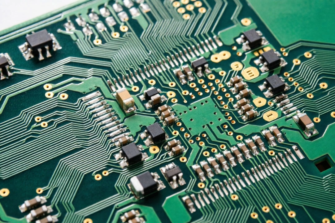
For example, micro-cracks or crazing in the base laminate material might be acceptable in lower classes if they don't expose conductors. But in Class 3? They are usually rejected outright. Why? Because under thermal shock, a microscopic crack can easily propagate and cause an open circuit. Also, annular ring breakout is generally unacceptable. You need a minimum ring of 0.05mm around your vias to ensure the connection stays solid even if the drill wanders slightly during manufacturing.
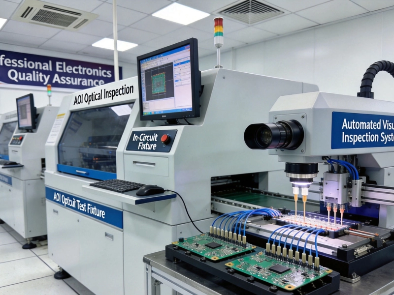
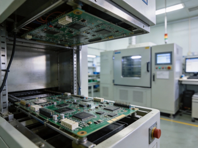
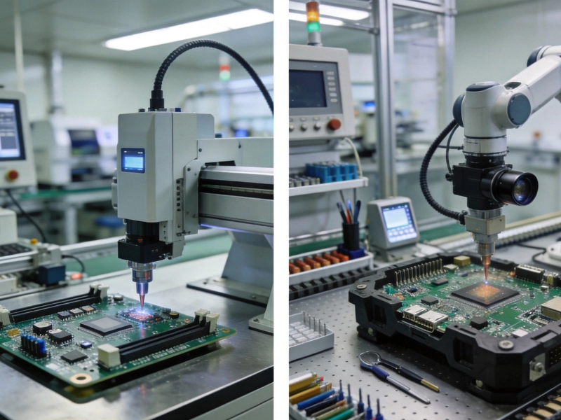
Thermal and Mechanical Stress TestingYou can't just trust the visual inspection. Real reliability comes from brutal testing. When Understanding IPC Class 3 Standards for High-Reliability Industrial PCBs, thermal stress tests are mandatory. Boards are often baked at 125°C for an hour and then subjected to solder float tests to simulate assembly heat.
Beyond heat, mechanical strength is huge. High-reliability boards must survive intense vibration without fracturing solder joints. This is why component placement matters so much. Heavy parts like large electrolytic capacitors need adhesive or special brackets. If you are designing these boards, always avoid 90-degree trace corners; use 45-degree angles or curves to prevent stress concentration points. A little bit of smart layout goes a long way in passing those harsh qualification tests.
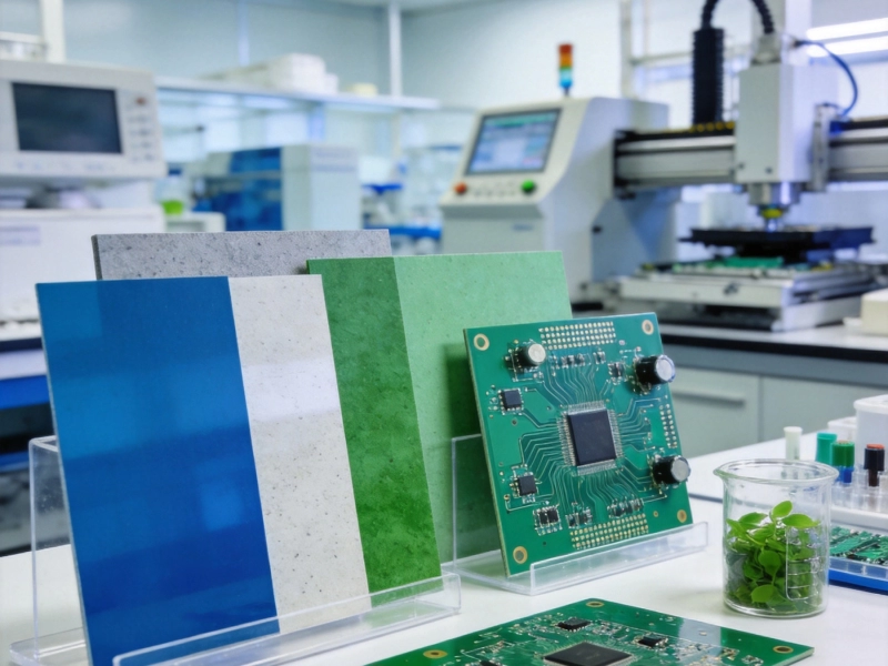
Material Selection for Extreme EnvironmentsStandard FR-4 just doesn't cut it here. For industrial applications facing high heat, you need
High-tg Materials (
Glass Transition Temperature above 170°C). Regular FR-4 starts getting soft and losing dimensional stability around 130°C. Imagine what happens inside an engine bay or near a power converter!
Also, Conductive Anodic Filament (CAF) resistance is critical. CAF is an invisible killer where copper migrates through the glass fibers in humid conditions, causing internal shorts. Class 3 boards require specialized resins and treatments to prevent this. Always verify that your supplier uses CAF-resistant laminates if your product will face harsh humidity.
Why Cutting Corners is a Bad IdeaSometimes procurement teams push back on the price of Class 3 boards. But when Understanding IPC Class 3 Standards for High-Reliability Industrial PCBs, you realize that the upfront cost saves massive field failures. Lower classes mean higher defect density allowances, looser impedance control, and thinner plating.
A cheaper board might save $5 per unit, but if one fails in a remote wind turbine or a hospital MRI machine, the service call, replacement, and reputational damage will cost tens of thousands. Never compromise on the critical safety margins defined by IPC-6012 Class 3.
Conclusion: Designing with ConfidenceUnderstanding IPC Class 3 Standards for High-Reliability Industrial PCBs isn't just about reading a rulebook; it's about adopting a culture of quality. From thicker copper plating and strict annular rings to
High-tg Materials and rigorous thermal testing, every detail serves one purpose: absolute reliability.
If you're designing or sourcing mission-critical hardware, make sure your manufacturer is fully certified and experienced with Class 3. Don't hesitate to ask for cross-section reports and thermal stress test data. Your future self (and your customers) will thank you.
Frequently Asked QuestionsQ: Can I upgrade a Class 2 board to Class 3?A: Not really. Class 3 requires different materials, tighter process controls from the start, and stricter inspection criteria. You usually have to redesign and requalify.
Q: What is the biggest failure point in non-compliant boards?A: Barrel cracks in plated through-holes due to insufficient copper thickness or poor adhesion during
Thermal Cycling.
Q: Does Class 3 apply to software?A: No,
Ipc Standards are strictly for hardware manufacturing, materials, and physical assembly. However, hardware reliability enables software stability.