

Industrial printed circuit boards power the automation systems, motor drives, safety controllers, and communication infrastructure that keep factories, utilities, and transportation networks operating. When an Industrial Pcb fails, the consequences extend far beyond a single product malfunction. Production lines halt. Processes interrupt. Equipment operators face safety risks. The economic impact of field failures frequently dwarfs any component or manufacturing cost difference between a board that passes quality checks and one that doesn't. This reality makes quality assurance not merely a manufacturing concern but a business-critical discipline that deserves executive attention and adequate resource allocation.
Yet quality assurance for industrial PCBs presents challenges that differ fundamentally from consumer electronics quality management. Longer product lifecycles demand reliability measured in decades rather than years. Harsher operating environments stress boards beyond the limits consumer electronics never encounter. Regulatory compliance requirements bind certain industrial applications to documented quality processes that consumer markets never impose. Building a quality assurance plan that addresses these unique requirements demands systematic thinking about inspection strategy, testing protocols, supplier management, and Continuous Improvement.

Before designing a quality assurance plan, teams must understand what "quality" means for their specific industrial applications. The definition extends far beyond electrical continuity and cosmetic appearance into domains of reliability, durability, and documentation traceability.
Industrial Pcb quality encompasses several distinct dimensions. Electrical quality means boards that function correctly within specification boundaries—proper Impedance Control, adequate insulation resistance, and reliable signal transmission. Mechanical quality means boards that withstand physical stress without Delamination, cracked traces, or interconnection failures. Environmental quality means boards that survive temperature extremes, humidity exposure, vibration, and chemical contact without degradation. Process quality means manufacturing records documenting exactly how each board was built, enabling Failure Analysis and regulatory compliance.
The relative importance of these dimensions varies by application. An automotive engine control unit prioritizes vibration resistance and Thermal Cycling tolerance. A chemical plant sensor module prioritizes Chemical Resistance and humidity tolerance. A railway signaling system prioritizes long-term reliability and documentation traceability above almost everything else. Quality plans must weight these dimensions according to actual application requirements rather than treating all quality dimensions as equally important.
Effective quality assurance begins with explicit quality objectives that provide clear targets for the organization to pursue. Vague intentions to "make good boards" produce inconsistent results. Quantified objectives enable objective assessment of whether quality efforts succeed.
Defect rate targets should reflect both internal manufacturing capability and customer expectations. Many Industrial Pcb programs target defect rates below 1%, with some demanding programs requiring rates below 0.1%. These targets must be realistic given current capability—unrealistic targets demotivate teams who see the goal as perpetually unattainable. Start with achievable targets, measure performance honestly, and tighten objectives as capability improves.
First-pass yield targets measure the percentage of boards that pass all inspections and tests without rework. Higher first-pass yield directly reduces manufacturing cost by minimizing scrap, rework labor, and retest efforts. Industrial Pcb programs typically target first-pass yields above 95%, with mature high-volume programs often exceeding 98%.
Field failure rate targets extend quality measurement beyond manufacturing into product lifecycle performance. Customer warranty data, service records, and returned Failure Analysis all contribute to understanding field reliability. Industrial programs should track field failure rates with enough granularity to identify failure patterns—specific board types, failure modes, or customer applications that show elevated failure rates.
Process capability indices provide statistical measures of manufacturing consistency. Cpk measurements for critical parameters (impedance tolerance, plating thickness, via resistance) quantify whether processes center within specification limits and vary within acceptable ranges. Industrial quality systems typically require Cpk above 1.33 minimum for critical parameters, with higher targets for more demanding applications.
The quality of incoming materials fundamentally constrains the quality of finished boards. Inspecting materials before they enter production prevents defective inputs from consuming manufacturing resources and potentially reaching customers.
Pcb Substrate inspection verifies that laminate materials meet specification requirements. Key parameters include dielectric thickness, copper weight, Glass Transition Temperature (Tg), and Dielectric Constant for high-frequency materials. Visual inspection checks for surface defects, contamination, or handling damage. Electrical testing on coupon samples verifies dielectric properties.
Copper-clad laminate testing should include impedance measurements on test traces fabricated from incoming material. This verification confirms that dielectric properties match supplier specifications and enables process adjustments before production runs consume expensive materials. Material certification documents provide supplier data, but independent verification catches certification errors or material substitutions.
Component verification for industrial PCB assemblies ensures that received components match purchase specifications. Visual inspection verifies package type, markings, and physical condition. Sampling-based electrical testing confirms that components function within datasheet specifications. Counterfeit component risk in some supply chains demands particular attention—verifying component authenticity through authorized distribution channels provides protection that inspection cannot match.
Solder paste and process chemicals require shelf-life verification and storage condition confirmation. Expired or improperly stored materials produce inconsistent assembly results. Maintain chemical inventory management systems that track lot numbers, expiration dates, and storage conditions.
PCB Fabrication involves dozens of sequential process steps, each presenting opportunities for defect introduction. Effective quality assurance establishes controls at each critical step that prevent defects rather than merely detecting them after completion.
Automated Optical Inspection (Aoi) provides real-time defect detection during and after fabrication. Modern Aoi systems detect shorts, opens, insufficient clearance, and copper defects with high reliability. Configure AOI inspection criteria to match design rules—minimum line width, minimum spacing, annular ring requirements—and verify that the system catches deliberate test defects to confirm detection capability.
Impedance testing validates that controlled-impedance traces meet specified tolerances. Test coupon structures fabricated alongside production panels provide measurement access without consuming functional board area. Document impedance measurements with statistical process control charts that reveal process trends before out-of-tolerance conditions occur.
Cross-section analysis of representative samples verifies internal structures that visual inspection cannot access. Plated-through hole quality, microvia barrel plating, and multilayer interface integrity all require destructive examination. Establish sampling plans that balance inspection coverage against sample consumption—typically one cross-section per panel for qualification, with periodic verification throughout production runs.
Thermal stress testing exposes boards to rapid temperature cycling that reveals latent manufacturing defects. Float-zone immersion tests and thermal shock chambers identify Delamination, measling, and barrel cracking that might not manifest until field Thermal Cycling. Ipc Standards specify test conditions and acceptance criteria appropriate for different quality levels.
Pcb Assembly—applying solder paste, placing components, and forming solder joints—concentrates defect opportunities in ways that demand equally concentrated quality attention.
Solder paste inspection before component placement catches printing defects before they become assembly defects. 3D solder paste inspection systems measure paste volume, height, and shape, detecting insufficient paste, excess paste, or bridging that would cause assembly defects. This inspection investment pays back through reduced rework and improved first-pass yield.
Component placement verification confirms that components land in correct positions with correct orientation. Vision systems on modern pick-and-place equipment provide placement monitoring, but dedicated verification catches placement errors that equipment monitoring might miss.
Reflow profile monitoring ensures that assembly thermal exposure follows qualified parameters. Thermocouple mapping of production panels during initial setup confirms that oven profiles achieve target temperatures at board locations. Ongoing monitoring with thermocouple coupons verifies consistency throughout production runs. Profile deviations cause defects that inspection might miss—voids, head-in-pillow conditions, or incomplete reflow that cause field failures without manufacturing detection.
Post-reflow AOI detects component placement errors, solder bridging, insufficient solder, and tombstoning that occur during the reflow process. Configure AOI criteria to balance detection sensitivity against false positive rates—excessive sensitivity creates inspection bottlenecks while insufficient sensitivity allows defects to escape.
Electrical testing validates that boards perform their intended functions, catching defects that visual inspection cannot detect.
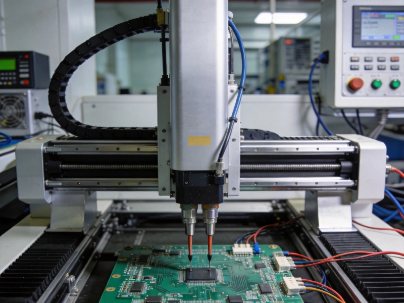
In-Circuit Testing (Ict) verifies individual component presence and values, detecting opens, shorts, missing components, and wrong values. Bed-of-nails fixtures provide access to Test Points, requiring design-for-testability provisions during layout. Ict typically achieves greater than 95% defect coverage for board-level defects, making it a cornerstone of Industrial Pcb Quality assurance.
Boundary Scan Testing addresses the growing proportion of board defects that ICT cannot access—particularly BGAs and other bottom-terminated packages. Boundary Scan leverages JTAG interfaces built into many ICs to verify interconnections without physical probe access. Implementing boundary scan requires design-for-test provisions but enables defect coverage that would otherwise require expensive Functional Testing.
Functional Testing verifies that boards perform intended functions—powering up correctly, responding to inputs, generating outputs, and communicating with system interfaces. Functional test procedures should reflect actual customer usage scenarios, exercising board functions in realistic patterns rather than artificial test sequences. Define test coverage objectives and verify that test procedures achieve those coverage levels.
High-Pot Testing (Hipot) verifies insulation resistance and Dielectric Strength for boards operating at elevated voltages. Industrial equipment with power supply sections, motor drives, or high-voltage sensing requires hipot testing to verify that insulation spacing and material properties prevent dangerous leakage or breakdown. Define test voltages, current limits, and dwell times appropriate for board voltage ratings and applicable safety standards.
As board complexity increases, basic inspection techniques prove insufficient for comprehensive quality assurance. Advanced inspection technologies address defect types that conventional methods cannot reliably detect.
X-ray Inspection penetrates board structures to reveal internal features invisible to optical inspection. BGA solder joint quality, QFN bottom-side connections, and Buried Via structures all require X-ray examination. 2D X-ray provides projection images suitable for void detection. 3D computed tomography reconstructs volumetric images enabling detailed internal analysis. Invest in X-ray capability when board designs include bottom-terminated components or complex internal structures.
Acoustic Micro-Imaging (C-SAM) uses ultrasonic waves to detect delamination, voids, and moisture ingress within board structures. Different materials reflect ultrasound differently, creating image contrast that reveals interface failures. C-SAM proves particularly valuable for identifying moisture-related delamination risks and verifying lamination quality in multilayer boards.
Time Domain Reflectometry (TDR) locates impedance discontinuities along traces by analyzing reflections from test pulses. While primarily a design validation tool, TDR can identify manufacturing variations that create impedance deviations beyond acceptable limits. Implement Tdr Testing for boards with tight controlled-impedance requirements, particularly those operating above 5Gbps.
Infrared Thermography detects localized heating that indicates high-resistance connections, uneven current distribution, or material defects. While less common than other inspection methods, thermography can identify problems that electrical testing misses—particularly intermittent contacts that pass static tests but fail under load.
Industrial Pcb Quality assurance extends beyond defect detection into documentation systems that enable failure analysis, regulatory compliance, and Continuous Improvement.
Lot traceability links finished boards to their constituent materials and manufacturing processes. When a defect emerges in fielded boards, traceability records identify which production lots of materials and which manufacturing parameters might have contributed. Implement traceability at a granularity appropriate for your failure analysis needs—typically at panel or batch level, with component date/lot traceability for critical components.
Manufacturing traveler systems document the specific processes each board undergoes. Equipment calibration records, process parameter logs, operator certifications, and inspection results all attach to traveler records. These documents answer questions about "how was this board made" that generic process descriptions cannot address.
Nonconformance reporting (NCR) systems capture defect information when inspection or testing detects anomalies. NCR records document the specific defect observed, its location, quantity affected, and disposition taken. Track NCR trends over time to identify systematic problems requiring process improvement rather than individual board rejection.
Corrective and preventive action (CAPA) processes close the loop between defect detection and systemic improvement. When NCR data reveals patterns, investigate root causes and implement corrective actions that prevent recurrence. Verify that corrective actions achieve intended effects before closing CAPA records. Preventive actions address potential problems before they manifest as defects.
Industrial PCB quality depends heavily on supplier performance—both PCB fabricators and component distributors. Building supplier quality capability protects your product quality investment.
Supplier qualification processes verify that new suppliers can meet quality requirements before production commitments. Audit supplier quality systems, review process capability data, and conduct capability assessments that verify they can achieve your specifications. Request sample boards that undergo full qualification testing before approving production orders.
Supplier performance monitoring tracks quality metrics throughout the supplier relationship. Defect rates, on-time delivery, responsiveness to quality issues, and documentation completeness all contribute to supplier scorecards. Conduct regular business reviews that assess overall supplier health, not just individual transaction issues.
Supplier development programs help key suppliers improve quality capability when gaps exist. Share defect data, provide technical guidance, and collaborate on process improvements that benefit both parties. Suppliers who receive development support often become more reliable partners than those who face only scorecard penalties.
Incoming inspection sampling plans balance inspection coverage against inspection cost. Zero-defect supplier programs may justify reduced incoming inspection for suppliers with demonstrated capability. Higher-risk suppliers or critical components warrant more intensive incoming verification. Adjust sampling based on supplier history and component criticality.
Quality assurance cannot fully compensate for designs that are difficult to manufacture reliably. Integrating quality considerations into design practices reduces manufacturing defects at their source.
Design For Manufacturability (DFM) reviews evaluate designs against fabrication and assembly capabilities before releasing to production. DFM checklists verify that feature sizes, tolerances, and complexity levels match supplier capabilities. Schedule DFM reviews at design milestones when changes remain affordable—late-design DFM findings may be too expensive to implement.
Design For Testability (Dft) provisions enable effective testing that catches defects efficiently. Test point accessibility, boundary scan implementation, and functional test provision all require design decisions that affect test coverage and defect detection. Invest in Dft during design—test-equivalent redesigns cost far more than upfront test provisions.
Parts library management ensures that designers use components with proven manufacturing history. Avoid first-use components without qualification—new components may have hidden manufacturing issues that appear only in volume production. Establish part approval processes that require manufacturing qualification before design use.
Design rule checking (DRC) automates verification that layouts comply with manufacturing constraints. Configure DRC rules to match fabricator capabilities, not generic industry standards. Automated verification catches rule violations that manual review misses, particularly on complex multilayer boards.
Industrial boards must survive environmental conditions far harsher than consumer electronics typically encounter. Environmental Testing validates that designs and manufacturing processes deliver required reliability.
Thermal cycling testing accelerates the Thermal Fatigue mechanisms that cause field solder joint failures. Define temperature range based on expected field conditions—industrial equipment might cycle between -40°C and +85°C. Ipc Standards specify test cycle counts and acceptance criteria, but mission-specific requirements may demand extended testing beyond standard levels.
Temperature Humidity Bias (THB) testing evaluates reliability in humid environments where moisture ingress causes electrochemical failures. Elevated temperature and humidity accelerate moisture-related degradation mechanisms that would take years to manifest at ambient conditions. Industrial equipment for outdoor or process-industry applications typically requires THB qualification.
Vibration testing verifies mechanical robustness for boards subject to continuous vibration. Random vibration profiles simulate transportation and operational vibration environments. Vibration testing may reveal resonances, loose component mounting, or solder joint fatigue that thermal cycling alone would not detect.
HALT (Highly Accelerated Life Testing) pushes boards beyond specified limits to identify failure modes and design margins. HALT deliberately operates boards past specification boundaries, ramping stress levels until failure occurs. The resulting failure modes reveal weaknesses that standard qualification testing might not detect. Use HALT during development to strengthen designs before production release.
Preventing defects proves more cost-effective than detecting and rejecting defective boards. Statistical process control (SPC) enables proactive quality management that catches process drift before it produces defects.
Process monitoring tracks key parameters throughout manufacturing. Impedance measurements, plating thickness, solder paste volume, and reflow temperatures all contribute to SPC charts that reveal whether processes remain in control. Establish control limits based on process capability studies, not arbitrary round numbers.
Control chart interpretation distinguishes between random variation (process in control) and systematic variation (process out of control). When control charts show trends, shifts, or unusual patterns, investigate before defects occur. Early intervention prevents defect escapes while maintaining low scrap rates.
Process improvement initiatives use SPC data to target improvement efforts. Pareto analysis of defect data identifies the failure modes causing most quality losses. Concentrating improvement on top Pareto items delivers maximum return on improvement investment.
Measurement system analysis verifies that inspection and test equipment produces reliable data. Gauge repeatability and reproducibility (R&R) studies quantify whether measurement variation dominates process variation. When measurement systems are unreliable, quality data becomes noisy and decisions suffer. Invest in measurement capability before expanding SPC programs.
Quality assurance systems must evolve as products, technologies, and customer requirements change. Building continuous improvement into quality operations prevents stagnation and enables responsiveness to new challenges.
Quality metrics dashboards provide visibility into quality performance across the organization. Track defect rates, first-pass yield, field failure rates, and CAPA cycle times. Display metrics where teams can see them—quality performance boards on manufacturing floors, management dashboards for leadership reviews. Visibility drives accountability.
Root cause analysis training builds organizational capability to address quality problems systematically. Techniques like 8D problem solving, fishbone diagrams, and 5-why analysis provide structured approaches to finding true causes rather than treating symptoms. Invest in training that builds quality problem-solving capability across the organization.
Lessons learned processes capture insights from both quality successes and failures. Document what worked, what didn't, and why when implementing quality improvements or responding to quality problems. Review lessons learned during new product development to prevent repeating past mistakes.
Technology scanning monitors emerging inspection and test technologies that might improve quality capability. X-ray computed tomography, advanced AOI algorithms, and AI-assisted defect classification all represent capability improvements worth evaluating. Balance innovation adoption against process stability—frequent technology changes disrupt established quality routines.
Quality assurance systems work only as well as the people operating them. Technical quality programs fail without cultural support that makes quality a shared organizational priority.
Quality leadership commitment sets the tone for organizational quality behavior. When leadership treats quality as negotiable versus cost or schedule, employees learn that quality doesn't truly matter. When leadership consistently prioritizes quality, employees internalize quality values that guide daily decisions.
Employee quality involvement harnesses frontline knowledge for improvement. Workers closest to manufacturing processes often see problems first and understand causes better than anyone else. Create channels for quality suggestions, recognize quality contributions, and act on employee insights.
Quality training programs build skills that enable quality performance. IPC certification for assembly operators, statistical methods training for engineers, and quality awareness for all employees each contribute to organizational quality capability. Maintain training records that document who has been trained and when.
Recognition and accountability balance positive reinforcement with appropriate consequences. Recognize teams and individuals who achieve quality goals, implement improvements, or demonstrate quality leadership. Address quality failures through systemic investigation rather than individual blame—blame cultures suppress reporting and hide problems.
Industrial PCB applications frequently encounter regulatory requirements that mandate specific quality practices. Navigating compliance obligations requires awareness and systematic processes.
IPC standards provide widely-recognized quality benchmarks for Electronics Manufacturing. Ipc-a-600 specifies acceptability criteria for printed boards. IPC-A-610 addresses Electronics Assembly workmanship. Ipc-6012 qualifies board fabrication processes for specific applications. Reference applicable IPC standards in quality plans and verify that processes meet specified requirements.
Industry-specific requirements apply to particular market segments. Automotive applications require Iatf 16949 quality management certification. Medical device applications must comply with FDA quality system regulations or EU MDR requirements. Railway and transportation applications may reference EN standards or specific customer requirements. Identify applicable standards and build compliance into quality plans.
Customer quality requirements often supplement industry standards with specific expectations. Major industrial customers frequently require supplier quality manuals, first article inspections, and process capability documentation. Manage customer requirements in a requirements management system that tracks compliance and changes.
Environmental compliance affects Material Selection and manufacturing processes. RoHS restrictions on hazardous substances, REACH chemical registration, and conflict mineral sourcing all influence quality practices. Maintain compliance documentation that demonstrates adherence to applicable environmental requirements.
New product introduction (NPI) presents unique quality challenges as designs transition from prototype to production. Quality plans should address NPI specifically.
Qualification testing protocols verify that new designs achieve quality targets before volume production begins. Define qualification test plans that exercise boards under worst-case conditions, not merely typical operating conditions. Require qualification pass criteria that reflect field requirements, not arbitrary pass/fail thresholds.
Production release criteria define the quality performance required before transitioning from pilot to volume production. Minimum first-pass yield, zero critical defect escapes, and process capability indices above targets all contribute to release decisions. Resist pressure to release production before meeting quality criteria—premature releases multiply quality problems across larger production volumes.
Process Parameter Validation confirms that production processes achieve qualification results consistently. Validate processes through capability studies that demonstrate Cpk meets targets, not just that sample boards passed qualification testing. Process validation protects against capability drift between qualification and production.
Design change management controls modifications to released designs. Every change carries risk of unintended consequences. Require quality impact assessment before implementing changes, and validate that changes don't degrade quality before deploying to production.
Understanding quality economics guides investment decisions in quality systems and improvement initiatives.
Prevention costs include quality planning, training, and process control investments that prevent defects from occurring. These investments typically offer the highest return on quality spending.
Appraisal costs include inspection, testing, and evaluation activities that detect defects after they occur. While necessary, appraisal costs should decrease as prevention investments take effect.
Internal failure costs include scrap, rework, and retest expenses when defects are detected before shipment. These costs represent waste that prevention investments can eliminate.
External failure costs include warranty claims, field service, and customer dissatisfaction when defective boards reach customers. These costs often dwarf all others combined, making prevention investment economically compelling.
Track cost of quality metrics to identify opportunities for improvement. When internal and external failure costs are high relative to prevention costs, increasing prevention investment typically reduces total quality cost while improving quality outcomes.
Implementing a robust quality assurance plan for industrial PCBs requires integrating technical processes, organizational culture, and business economics into a coherent system. No single element suffices alone—quality plans fail when technical excellence meets cultural indifference, or when cultural commitment meets inadequate processes. The best industrial PCB quality systems combine skilled people, capable processes, advanced technology, and continuous improvement into a self-reinforcing system that consistently delivers boards meeting application requirements. This investment pays returns through reduced field failures, lower warranty costs, satisfied customers, and competitive differentiation that quality-focused industrial equipment buyers increasingly demand.
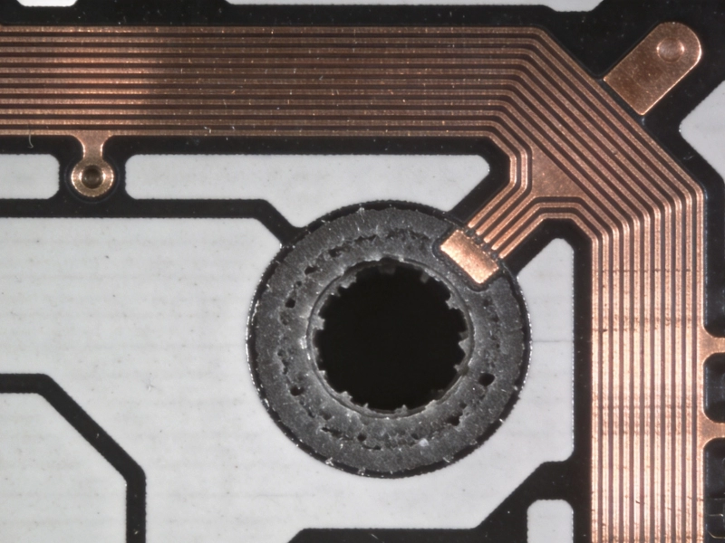
Identifying and Fixing Micro-Vias Issues in Industrial PCB Quality InspectionsSeptember/10/2026
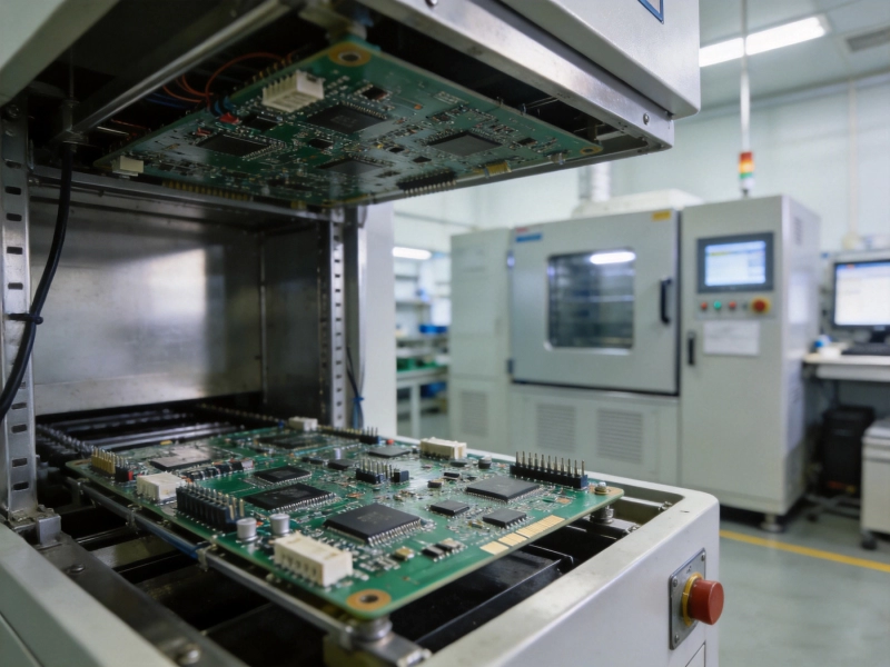
Environmental Stress Screening (ESS) for Validating Industrial PCB QualityAugust/08/2026
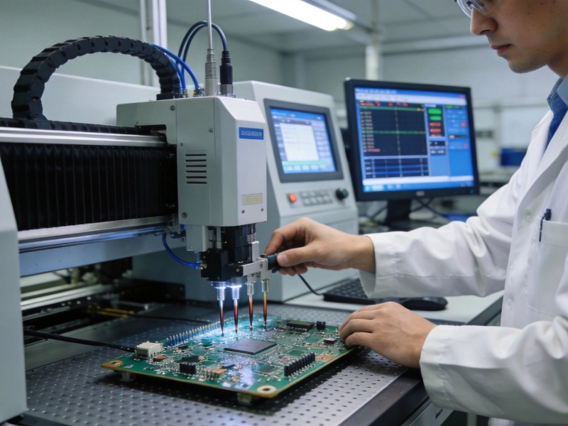
Why Electrical Testing is Non-Negotiable for Industrial PCB QualitySeptember/29/2026

The Impact of Surface Roughness on High-Speed Signal IntegrityOctober/13/2026
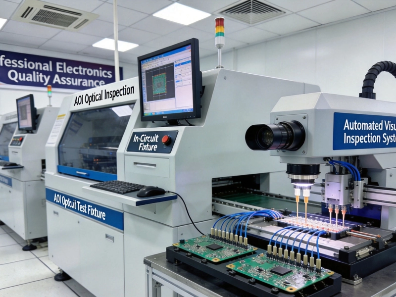
Essential Quality Control Tests for Industrial PCBs- ICT, FCT, and AOIMay/27/2026

Understanding IPC Class 3 Standards for High-Reliability Industrial PCBsJune/11/2026
The Role of Flying Probe Testing in Industrial PCB Quality ControlJuly/22/2026

The Rise of Halogen-Free Industrial PCB Materials: Benefits and Trade-offsAugust/06/2026