Open Nav


Industrial automation environments punish electronic components relentlessly. Conveyor systems shake machinery during high-speed operation. Robotic arms decelerate with violent force when picking and placing products. Presses and hammers generate repetitive impact loads that travel through mounting structures into every circuit board. Without proper design considerations, printed circuit boards in these environments fail prematurely, causing costly downtime and lost production. This guide examines the science of vibration and shock resistance, providing practical strategies for designing PCBs that survive the demanding conditions of industrial automation.
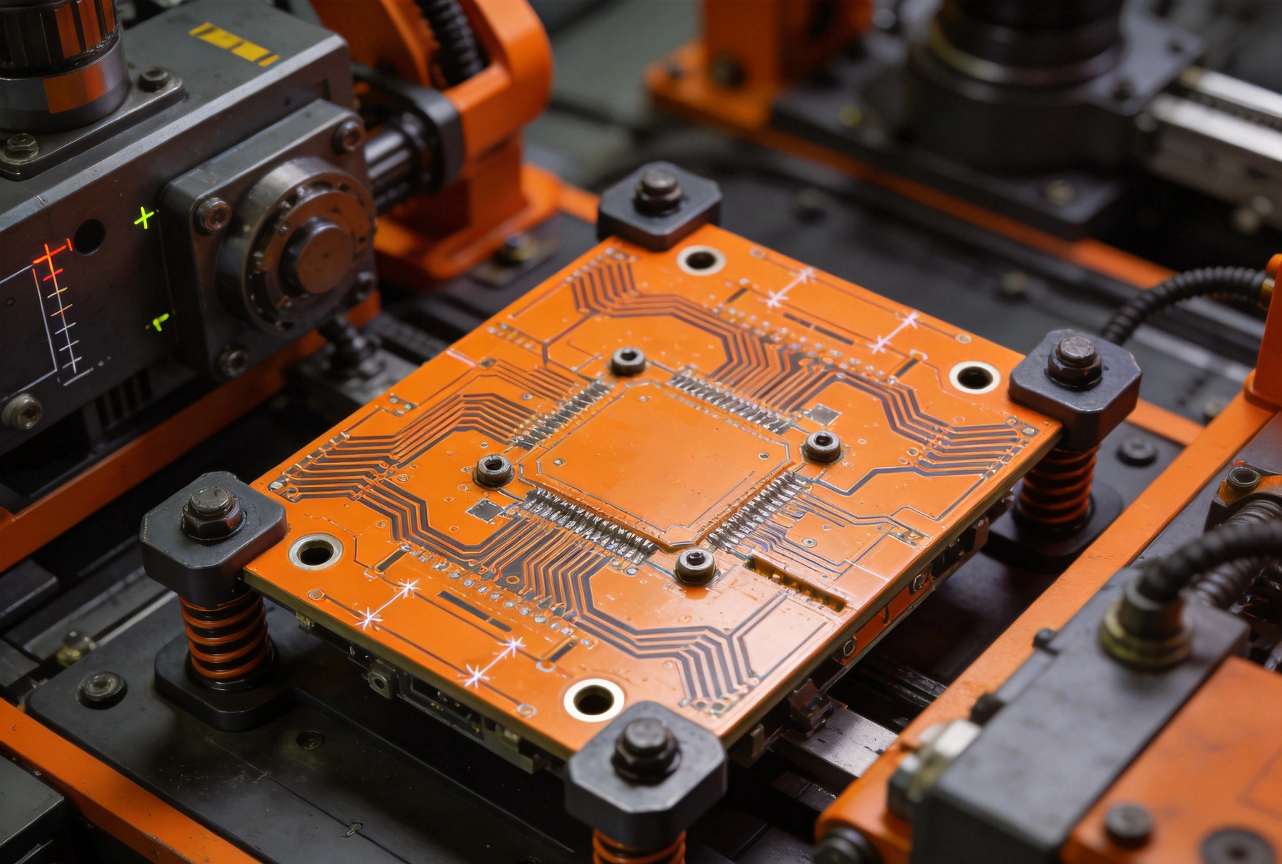
Vibration refers to oscillatory motion that repeats over time. Industrial equipment generates vibration across a wide frequency spectrum, from low-frequency rumble at 5-20 Hz to high-frequency tremor above 2000 Hz. Shock events deliver single or multiple high-energy impulses, sometimes exceeding hundreds of Gs in magnitude.
The severity of these environmental factors varies dramatically across automation applications. Robotic work cells experience moderate continuous vibration combined with intermittent shock during arm movements. CNC machining centers generate powerful vibration during cutting operations. Pneumatic actuators produce rhythmic pulses that transmit through mounting surfaces. Packaging equipment subjects boards to repeated shock during product handling cycles.
Engineers must characterize these environments before designing countermeasures. Acceleration, velocity, and displacement measurements reveal the magnitude and frequency content of vibrational energy. Shock pulse duration and shape determine the frequency distribution of impact loads. Understanding these parameters enables targeted design solutions rather than wasteful over-engineering.
Vibration and shock attack PCBs through several distinct failure mechanisms. Understanding these mechanisms guides effective design decisions.
Repeated cyclic stress eventually cracks solder joints. Leadless components like QFN and BGA packages prove particularly susceptible because their solder joints experience shear stress during board deflection. Vibration-induced fatigue cracks propagate gradually, causing intermittent connections that create mysterious operational failures. Eventually these cracks open completely, causing catastrophic failure.
The rate of fatigue accumulation depends on stress amplitude, frequency, and duration. Higher vibration levels accelerate damage. Resonance conditions amplify board deflection dramatically, creating stress levels orders of magnitude above non-resonant conditions. Careful mounting design prevents resonance excitation.
Ceramic capacitors and quartz crystals contain brittle materials that crack under shock loading. Physical impact can shatter these components entirely. Even when damage appears cosmetic, internal cracks may create reliability problems that manifest only after additional stress exposure.
Large heavy components experience greater inertial forces during vibration and shock. Transformers, heat sinks, and large electrolytic capacitors transmit substantial loads into their terminations. These forces stress solder joints and can pull components partially or completely off the board.
Extreme vibration levels stress PCB traces and pads directly. High-cycle fatigue can crack traces, particularly at acute angles where stress concentrates. Pads may lift from the board surface when cyclic stress exceeds adhesive strength. These failures create opens that interrupt signal paths or Power Distribution.
Board-to-board connectors experience relative motion during vibration. This motion causes wear on contact surfaces, eventually degrading connection quality. Fretting corrosion accelerates this degradation in environments with vibration combined with humidity or contamination.
How a PCB mounts to its supporting structure fundamentally determines its vibration exposure. Effective mounting design provides isolation from vibrational energy while maintaining adequate stiffness for electrical performance.
Rigid mounting directly to chassis structures transmits vibration directly into the board. standoff mounting provides some isolation, but standard threaded standoffs offer minimal vibration damping. Compression mounting between standoffs can improve damping characteristics.
elastomeric standoffs incorporate rubber or silicone elements that absorb vibrational energy. These mounts typically reduce resonance amplitudes by 10-20 dB, substantially decreasing fatigue damage rates. However, they introduce compliance that may create problems for boards with sensitive controlled-impedance traces.
Continuous clamping along board edges distributes mounting stress more uniformly than discrete point mounting. Aluminum extrusion channels with elastomeric inserts provide effective vibration isolation while maintaining firm retention. These systems accommodate thermal expansion without generating stress concentrations.
Cam-action latch systems enable quick board removal for service while providing secure clamping during operation. However, latches introduce variability in clamping force, potentially creating loose connections over time if not properly maintained.
Dedicated vibration isolation mounts incorporate elastomeric elements specifically designed for damping. These mounts feature shaped rubber elements that optimize energy absorption across relevant frequency ranges. Industrial-grade mounts survive millions of fatigue cycles without degradation.
Some applications benefit from viscous dampers that actively dissipate vibrational energy. These devices contain fluid chambers that generate heat as vibrational motion forces fluid through restricted passages. The energy converted to heat cannot damage the PCB. Viscous dampers prove particularly effective for low-frequency vibration and shock events.
Beyond mounting considerations, PCB construction itself significantly affects vibration tolerance. Several design strategies improve board robustness.
Breakaway tabs connecting individual boards to panel rails often create stress concentrations that propagate into components near tab boundaries. V-groove scoring concentrates stress during depanelization, potentially damaging nearby components. Routing tabs distribute stress more uniformly but require more panel space.
Planning depanelization sequence and locating vibration-sensitive components away from tab areas prevents manufacturing-induced damage. Automated depanelization equipment with controlled tooling reduces stress exposure compared to hand depanelization.
Heavy components should locate near mounting points where board deflection remains minimal. Distributing mass evenly prevents local stress concentrations. Locating tall components away from high-vibration areas reduces overturning moments that stress solder joints.
Placing flexible components like electrolytic capacitors in areas of low board strain improves reliability. Rigid components like ceramics tolerate higher stress levels. Strain gauges or FEA analysis identify optimal component locations for sensitive parts.
Stiffening bars attached to PCB edges substantially reduce resonance amplitudes. Aluminum or steel bars bonded or screwed to the board provide additional rigidity without major design changes. The attachment method must not introduce stress concentrations that defeat the reinforcement purpose.
Potting and Conformal Coating provide vibration damping while protecting components from contamination and handling damage. Soft silicone potting compounds effectively damp vibration without generating excessive stress during Thermal Cycling. Hard epoxies may amplify Vibration Damage by constraining thermal expansion.
Via-in-pad designs concentrate stress at solder joints, promoting crack propagation. Standard annular ring designs distribute stress more uniformly. For boards with significant vibration exposure, maximizing annular ring dimensions within manufacturing constraints improves long-term reliability.
Teardrop pad connections reduce stress concentrations at via-to-trace junctions. These rounded transitions eliminate sharp corners where stress concentrates. Most PCB CAD tools include automated teardrop generation features.
Pcb Substrate materials affect both mechanical stiffness and vibration damping characteristics. Material Selection requires balancing multiple performance factors.
Standard FR-4 epoxy-glass laminates provide adequate performance for moderate vibration environments. Higher-Tg FR-4 formulations maintain stiffness at elevated temperatures, improving resistance to vibration-induced damage in hot industrial environments.
Polyimide laminates offer superior thermal performance and improved flexibility tolerance. These materials survive more thermal cycles without degradation, indirectly improving vibration resistance by maintaining consistent mechanical properties.
Metal-core PCBs incorporate aluminum or copper substrates that dramatically improve Thermal Conductivity while providing exceptional stiffness. These boards tolerate higher vibration levels without excessive deflection. The thermal benefit enables compact designs that would otherwise require larger heat sinks.
Hybrid constructions combining rigid and flexible substrates accommodate vibration-induced movement while maintaining electrical connections. Rigid sections support components while flexible sections absorb vibrational energy. This approach proves effective for boards that must survive both extreme vibration and Thermal Cycling.
For extreme environments, ceramic substrates like alumina or aluminum nitride provide exceptional stiffness and Thermal Conductivity. However, these materials are brittle and require careful handling during manufacturing and assembly. The high material and manufacturing costs limit ceramic PCBs to applications where performance requirements justify the expense.
Designing for vibration resistance requires verification testing that confirms products survive intended environments. Testing protocols vary based on application requirements and industry standards.
Random vibration testing applies simultaneous frequencies across the spectrum, simulating real-world vibration exposure more accurately than single-frequency sweep testing. Test profiles specify acceleration spectral density across frequency ranges, typically from 20 Hz to 2000 Hz.
Industrial equipment tests commonly specify 1-5 Grms random vibration levels. Military and aerospace applications may require testing at 10-20 Grms or higher. Test duration typically ranges from hours for screening to days for qualification testing.
Shock testing applies controlled impact pulses to verify survival of sudden load events. The half-sine pulse shape simulates typical mechanical impacts. Drop testing applies shock through gravity acceleration during equipment handling.
Test levels and pulse shapes vary by application. Some standards specify the sawtooth or trapezoidal pulse shapes that excite different frequency content. Testing in multiple axes ensures comprehensive qualification.
Real-world vibration rarely occurs in isolation. Combined environment testing applies simultaneous temperature, humidity, and vibration stress that accelerates failure mechanisms compared to single-factor testing. This approach reveals interaction effects between environmental factors that separate testing might miss.
HALT testing applies progressively increasing stress levels until failure, identifying design margins and weak points. This destructive approach optimizes designs before formal qualification testing.
Experienced engineers recognize patterns in vibration-related failures. Avoiding common mistakes prevents costly field failures.
Overlooking board resonance creates catastrophic amplification of vibrational energy. Natural frequency analysis during design identifies potential resonance conditions before prototyping. Moving mounting points or adding stiffening changes resonant frequencies away from excitation sources.
Inadequate Strain Relief for cables and connectors concentrates vibration energy at board terminations. Flexible cable routing and cable clamp mounting reduce this stress transfer. Cable ties and clips should locate vibration-sensitive components away from cable entry points.
Using excessive adhesive creates stress concentrations as materials expand at different rates during thermal cycling. Soft adhesives work better than hard epoxies for vibration damping applications. Bond line thickness control ensures consistent damping characteristics across production boards.
Various industry standards define vibration and shock testing requirements for industrial equipment. Familiarity with relevant standards guides appropriate test planning.
IEC 60068 provides Environmental Testing procedures including vibration, shock, and bump testing methods. The standard defines multiple test severities appropriate for different equipment classes.
MIL-STD-810 establishes military environmental test methods originally developed for aerospace equipment. Many industrial applications adopt MIL-STD-810 test procedures due to their comprehensive nature and proven effectiveness.
Machine builder standards often specify vibration limits for electronic equipment mounted on specific machine types. Understanding these limits prevents specification mismatches between machine builders and component suppliers.
Vibration-resistant design increases product cost through specialized materials, additional components, and extended testing. Balancing cost against reliability requirements requires engineering judgment.
Applications where downtime costs exceed component costs justify premium vibration-resistant designs. Continuous process lines and unwatched equipment may justify additional investment in reliability. Short-lifetime products may tolerate higher failure rates if replacement costs remain acceptable.
Prototyping and testing costs mount quickly when qualifying vibration-resistant designs. Early design analysis using FEA tools identifies problem areas before physical prototypes. Virtual qualification reduces testing iterations and accelerates development.
Vibration and shock present serious challenges for Pcb Reliability in industrial automation applications. Successful designs require systematic consideration of mounting strategies, board construction, component selection, and qualification testing. Understanding failure mechanisms enables targeted countermeasures rather than wasteful over-engineering.
Modern industrial equipment demands exceptional reliability from electronic systems. Competitive pressure to reduce machine size and increase throughput intensifies vibration environments. Designing PCBs that survive these conditions separates leading automation suppliers from the competition.
The investment in vibration-resistant design pays dividends through reduced field failures, improved customer satisfaction, and lower warranty costs. For industrial automation applications, robustness is not optional—it is a fundamental requirement for market success.
Top 5 Causes of Failure and How to Improve Industrial PCB ReliabilitySeptember/21/2026
How to Prevent Electrochemical Migration (CAF) for Better Industrial PCB ReliabilitySeptember/04/2026
The Role of Conformal Coating in Enhancing Industrial PCB ReliabilityJuly/17/2026
Ensuring Industrial PCB Reliability in Extreme Environmental ConditionsMay/27/2026
Thermal Management Strategies for Long-Term Industrial PCB ReliabilityJune/04/2026
How to Enhance the Mechanical Strength of HDI StructuresSeptember/07/2026
A Comprehensive Guide to High-Tg Materials for Industrial PCBsJune/05/2026
Custom Industrial PCB Solutions for the Automotive SectorMay/27/2026