Open Nav


Industrial electronic systems operate in environments that would destroy consumer electronics within hours. From the scorching engine compartments of mining equipment to the freezing altitudes of high-altitude drones, from the corrosive salt spray on offshore platforms to the radiation-hardened circuits in space satellites—industrial PCBs must perform flawlessly where failure is not an option. This comprehensive guide explores how engineers and manufacturers ensure Pcb Reliability in the most demanding conditions on Earth and beyond.
When a medical device implanted in a patient fails, when an aircraft navigation system glitches at 35,000 feet, or when an autonomous mining truck stops dead in a remote location—the consequences extend far beyond simple product returns. Industrial Pcb reliability isn't just about quality metrics; it's about safety, mission criticality, and in many cases, human lives.
This guide provides engineering professionals, product designers, and procurement specialists with the knowledge needed to specify, design, and source PCBs that will survive extreme environmental challenges throughout their intended service life.
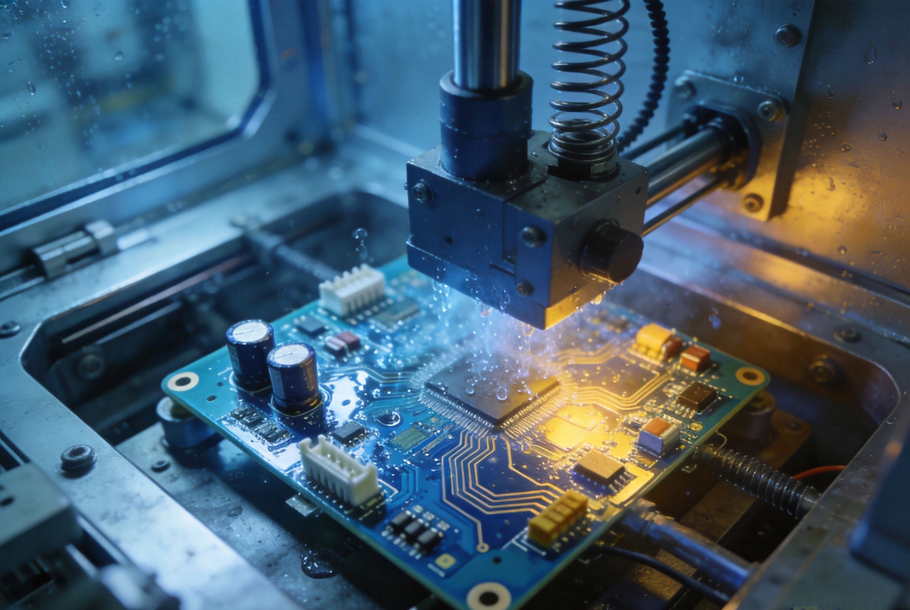
Before diving into solutions, we must understand the specific environmental stressors that challenge Pcb Reliability. Each environment presents unique degradation mechanisms that can cause premature failure if not properly addressed during design and manufacturing.
Temperature is often the most demanding environmental factor for industrial PCBs. Components and materials expand when heated and contract when cooled. When this happens thousands of times over a product's lifetime, the differential expansion rates between materials—copper, substrate, components, solder—create mechanical stress that leads to fatigue failures.
Cold Temperature Challenges:
High Temperature Challenges:
Downhole electronics face some of the most extreme temperature conditions on Earth. Wellbores can reach temperatures exceeding 200°C at depths below 10,000 meters. Standard commercial electronics rated to 85°C will fail within hours in these conditions. Even components rated to military temperature ranges (-55°C to +125°C) may not survive without specialized high-temperature Pcb Materials and extended burn-in testing.
Moisture is perhaps the most insidious environmental threat because it can infiltrate PCBs through microscopic pathways that are invisible to the naked eye. Once inside, moisture causes multiple failure mechanisms:
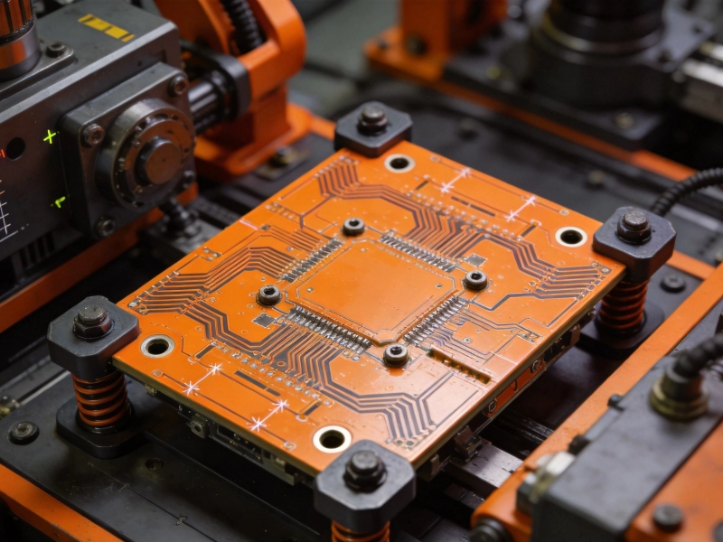
Industrial environments subject PCBs to vibration levels that would be unthinkable in consumer applications. Heavy machinery, transportation systems, and industrial equipment generate continuous vibration that stresses solder joints, loosens fasteners, and fatigues trace connections.
Key vibration considerations:
Chemical exposure—whether from industrial atmospheres, marine environments, or process chemicals—attacks Pcb Materials and components on multiple fronts:
For aerospace and high-altitude applications, radiation presents unique challenges:
Achieving reliability in harsh conditions requires proactive design decisions from the earliest stages of product development. Reactive approaches—adding protection after design completion—are almost always more expensive and less effective.
The foundation of extreme environment reliability begins with Material Selection. Different applications require different material properties:
| Material Type | Max Temperature | Key Properties | Typical Applications |
|---|---|---|---|
| Standard FR-4 (Tg 130-140°C) | 130°C | Cost-effective, widely available | Office environments, mild industrial |
| High-tg Fr-4 (Tg 150-180°C) | 170°C | Better thermal stability | Lead-free assembly, warm environments |
| Polyimide (Kapton) | 260°C+ | Excellent Thermal Resistance, flexible | Aerospace, high-temp industrial |
| Rogers RT/duroid | 200°C+ | Low loss, controlled dielectric | RF/microwave, aerospace |
| Aluminum Nitride | 400°C+ | High Thermal Conductivity | Power Electronics, LED lighting |
| Ceramic substrates | 600°C+ | Extreme temp capability | Downhole, aerospace combustion |
Managing heat is critical for reliability. Every 10°C reduction in operating temperature approximately doubles component lifetime. Design strategies include:
Thermal Vias: Arrays of plated through-holes under hot components transfer heat to internal ground planes or opposite surfaces.
Metal Core PCBs: Aluminum or copper cores spread heat rapidly away from heat-generating components.
Heat Spreadsers: Copper coin or metal backing plates distribute heat across larger areas.
Thermal Pads and Gap Fillers: Thermally conductive materials couple components to heat sinks or chassis.
Active Cooling Integration: Designing mounting provisions for fans or thermoelectric coolers when passive cooling is insufficient.
For high-vibration environments, mechanical reinforcement protects sensitive components:
When Thermal Cycling is unavoidable, design practices that minimize fatigue include:
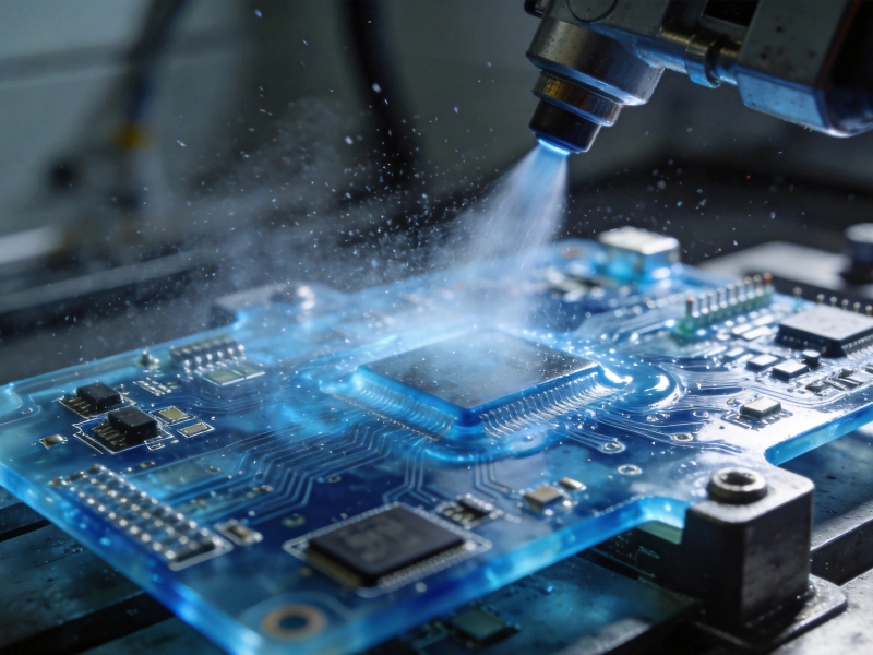
When environmental threats penetrate enclosures, conformal coatings and encapsulation provide the final defense for the PCB itself.
| Coating Type | Thickness | Temperature Range | Key Advantages | Limitations |
|---|---|---|---|---|
| Acrylic (AR) | 25-75 μm | -65°C to +125°C | Easy application/rework, good moisture resistance | Limited Chemical Resistance |
| Epoxy (ER) | 50-200 μm | -65°C to +150°C | Excellent Chemical Resistance, hard finish | Difficult to rework, thermal mismatch risk |
| Silicone (SR) | 50-200 μm | -65°C to +200°C | Wide temp range, flexible, good thermal shock | Soft surface, limited abrasion resistance |
| Urethane (UR) | 25-75 μm | -65°C to +130°C | Excellent chemical and moisture resistance | Requires precise application |
| Parylene (XY) | 12-50 μm | -65°C to +200°C | Ultra-thin, pinhole-free, excellent coverage | Specialized application equipment required |
For applications requiring maximum protection with minimal added mass or thermal impact, parylene Conformal Coating offers unique advantages. Applied via chemical vapor deposition, it forms truly conformal coverage that follows contours without pooling or voids. NASA and military specifications often require parylene for the most demanding applications. The trade-off is higher cost and the requirement for specialized application equipment.
For severe environments, full encapsulation provides superior protection at the cost of serviceability:
Design analysis and simulation are valuable, but nothing validates reliability like Accelerated Life Testing that compresses years of environmental exposure into weeks or months.
Boards are cycled between temperature extremes to accelerate fatigue mechanisms. Typical profiles:
Accelerated testing uses temperature extremes beyond field conditions and faster transition rates to compress test duration.
HALT deliberately pushes products beyond designed limits to identify failure modes and margins. Testing continues until the product breaks, then backs off to define operational and destruct limits. This testing finds weaknesses that accelerated steady-state testing misses.
Similar to HALT but applied to production units, HASS screens out infant mortality failures before products ship. HASS profiles are derived from HALT results and represent stress levels that catch defects without damaging good units.
85°C/85% Relative Humidity (often called "85/85 testing") accelerates moisture-related failures. Standard tests run for 1000-2000 hours, equivalent to years of field exposure in humid environments.
Random vibration profiles (per MIL-STD-810 or similar) simulate transportation and operational vibration. Shock testing applies high-G pulses that simulate impacts, drops, and pyrotechnic events.
Products designed for testability can be screened during production, catching defects before they reach customers. Key Dft features include:
Standards define minimum requirements and provide common language between designers, manufacturers, and customers. For extreme environment applications, these standards are not optional—they are essential:
The Automotive Electronics Council (AEC) standards define stress test qualifications for automotive-grade components:
For medical, automotive, aerospace, and safety-critical applications, using non-certified components or fabricators is not just risky—it's potentially illegal. Regulatory bodies (FDA, FAA, EMA) require documented compliance with recognized standards. Ensure your entire supply chain—from component vendors to assembly houses—holds appropriate certifications for your target market.
Sourcing PCBs for extreme environments requires extra scrutiny of your supply chain:
Not all fabricators can produce boards suitable for harsh environments:
Building PCBs for extreme environments costs more than standard commercial production. Understanding where to invest your reliability budget ensures maximum field success per dollar spent.
High-Return Investments:
Lower-Return Investments:
Extreme environment PCB reliability is not about using the most expensive components or the most exotic materials. It's about understanding your actual operating environment, designing appropriately for those conditions, and validating your designs through rigorous testing. Every industrial application has its own profile of environmental stressors—there's no one-size-fits-all solution, but there are proven approaches for every challenge.
Conformal coating is a thin protective film that follows the contours of the PCB and components, typically 25-200 microns thick. Potting or encapsulation fills the entire enclosure with material, completely surrounding and protecting the assembly. Conformal coating preserves some serviceability and adds minimal mass; potting provides maximum protection but makes repair nearly impossible. Choose coating for better Thermal Management and serviceability, potting for maximum protection against moisture, vibration, and physical damage.
Start with the actual maximum operating temperature you expect in the field, then add margin. Industry standards typically call for 20°C margin between maximum operating temperature and component temperature ratings. For automotive under-hood applications, you might need components rated to 150°C when the actual maximum operating temperature is 125°C. Consider not just steady-state temperature but also thermal cycling extremes and the temperature rise from self-heating.
Not necessarily. High-tg Materials have higher glass transition temperatures, which means they maintain mechanical stability at higher temperatures. However, they typically cost more and may have different electrical properties. For applications that never approach standard FR-4's Tg, paying extra for high-Tg provides no benefit. The right choice depends on your actual temperature requirements, lead-free assembly needs, and thermal cycling demands. Discuss your specific application with your fabricator.
This depends on your application and the vibration environment. Aerospace applications typically require random vibration testing per MIL-STD-810 at 6-12 Grms. Automotive engine compartment electronics see 20-50 Grms of sinusoidal vibration at frequencies up to 500 Hz. A board that passes 500 hours of random vibration testing at 6 Grms has demonstrated significant fatigue margin. Work with your Reliability Engineering team to define test levels based on your actual environment and expected service life.
For humid environments, the most cost-effective improvements typically are: (1) specifying an appropriate conformal coating rather than expensive hermetic packaging, (2) using ENIG surface finish instead of HASL for better corrosion resistance, (3) designing with wider spacing between traces to reduce creepage paths, and (4) specifying Pb-free solder with appropriate alloy (SAC305) for better long-term joint reliability. These changes are relatively modest in cost but address the most common humidity-related failure mechanisms.
Ensuring PCB reliability in extreme environmental conditions is both a science and an art. The science involves understanding material physics, failure mechanisms, and accelerated testing methodologies. The art involves balancing cost, performance, weight, and serviceability while making appropriate trade-offs for your specific application.
The most reliable products result from engineering teams that understand their environmental challenges from the start, select materials and components appropriate for those conditions, design with manufacturability and testability in mind, and validate their designs through rigorous Accelerated Life Testing.
Whether you're designing electronics for the depths of a coal mine, the vacuum of space, the deck of an offshore platform, or the engine compartment of an electric vehicle—the principles remain the same. Understand your environment, design appropriately, validate thoroughly, and source from qualified suppliers who share your commitment to reliability.
The cost of building reliable products is real, but the cost of field failures—in reputation, warranty claims, safety incidents, and lost customers—is almost always higher. Invest in reliability upfront, and you'll save both money and heartache over the product's lifetime.
How to Prevent Electrochemical Migration (CAF) for Better Industrial PCB ReliabilitySeptember/04/2026
How to Enhance the Mechanical Strength of HDI StructuresSeptember/07/2026
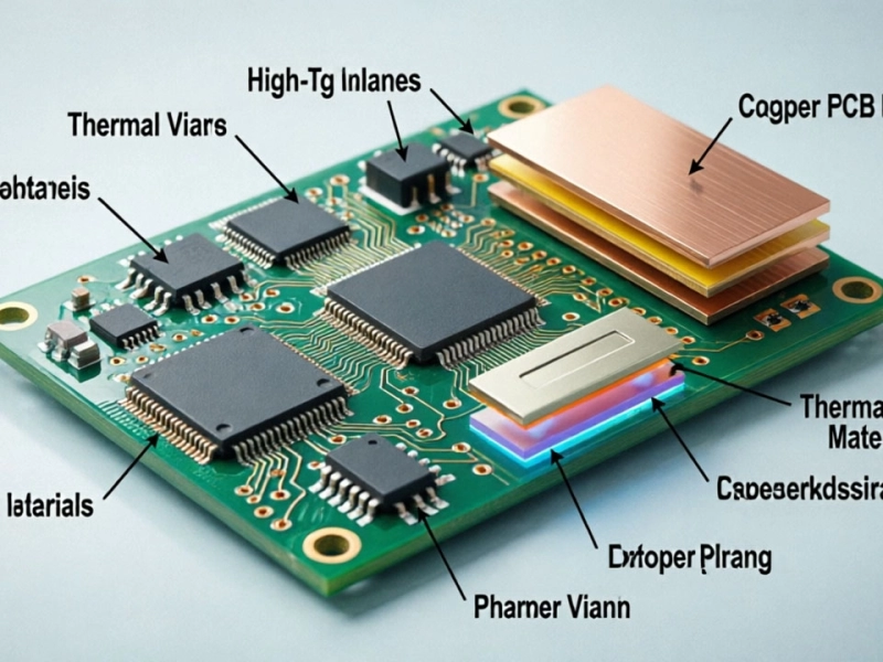
Thermal Management Strategies for Long-Term Industrial PCB ReliabilityJune/04/2026
Vibration and Shock: Designing for Industrial PCB Reliability in AutomationJune/30/2026
The Role of Conformal Coating in Enhancing Industrial PCB ReliabilityJuly/17/2026
Top 5 Causes of Failure and How to Improve Industrial PCB ReliabilitySeptember/21/2026
Why Choose Rigid-Flex PCB Solutions for Complex Industrial Assemblies?June/17/2026
Industrial PCBA: Navigating the Complexities of Box Build AssemblyJune/09/2026