Open Nav


Wrong PCB material choice causes Signal Integrity failures, unpredictable performance, and expensive redesigns in industrial applications.
High-speed industrial PCBs face harsh environments while maintaining precise Signal Integrity. Industrial Automation, industrial IoT, and advanced manufacturing systems demand Pcb Materials that deliver reliable performance under extreme conditions. Standard FR4 materials often fail to meet requirements, leading to signal degradation, timing errors, and system failures.
This comprehensive guide explores PCB Material Selection for high-speed industrial applications, covering dielectric properties, signal integrity considerations, material comparisons, and application-specific recommendations.
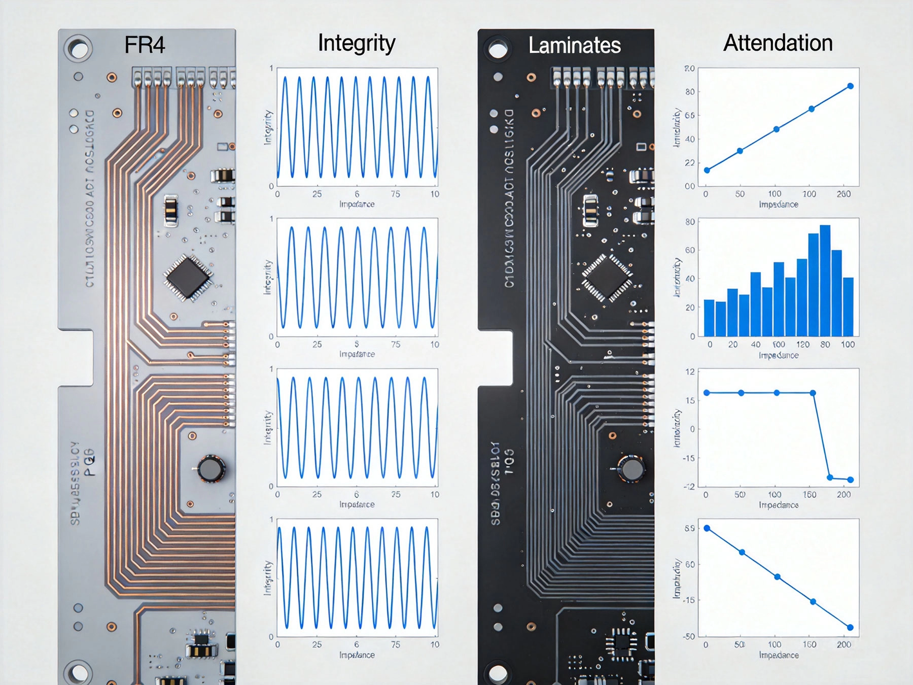
Industrial environments impose unique demands beyond typical High-speed Pcb applications:
Material Selection depends on understanding electrical properties that affect high-speed performance:
Dielectric constant (Dk) determines signal propagation velocity and impedance:- Impact: Higher Dk slows signals and reduces impedance- Desired characteristics: Low, stable Dk across frequency and temperature- Typical values: FR4: 4.0-4.8; Advanced laminates: 2.8-4.2- Stability requirement: Dk variation should be less than ±2% across frequency range
High-speed signals require consistent Dk to maintain impedance matching. Materials with Dk that varies with frequency cause dispersion, distorting signal edges.
Dielectric loss tangent (Df) represents signal attenuation through the material:- Impact: Higher Df causes greater signal loss, especially at high frequencies- Desired characteristics: Very low Df, ideally below 0.003 at 10 GHz- Typical values: FR4: 0.02-0.03; Advanced laminates: 0.001-0.005- Frequency dependence: Df increases with frequency in most materials
Low Df is critical for maintaining signal integrity over long distances. Losses compound with frequency, making high-speed signals especially vulnerable.
Moisture absorption affects both electrical and mechanical properties:- Electrical impact: Increases Dk and Df, degrading signal integrity- Mechanical impact: Causes dimensional changes and Delamination- Industrial challenge: Humidity cycling common in industrial environments- Desired characteristics: Below 0.5% moisture absorption
Thermal properties determine performance under temperature extremes:- Glass Transition Temperature (Tg): Temperature where material softens- Decomposition temperature (Td): Temperature where material degrades- Thermal expansion: Dimensional changes with temperature- Desired characteristics: Tg above 170°C, minimal thermal expansion
Industrial environments expose PCBs to various chemicals:- Resistivity to oils: Common in manufacturing environments- Solvent resistance: Cleaning chemicals may contact PCBs- Flux residue resistance: Post-soldering cleaning chemicals- Desired characteristics: Chemical compatibility with industrial cleaning agents
FR4 (Flame Retardant 4) remains the most common PCB material, but has significant limitations for high-speed industrial applications:
FR4 works for less demanding industrial applications:- Signal speeds below 1-2 GHz- Short trace lengths (< 10 inches) - Temperatures below 100°C - Low humidity environments - Cost-sensitive applications
Advanced laminate materials provide superior electrical performance:
Polyimide laminates excel in harsh industrial environments:- Temperature tolerance: Tg exceeds 250°C- Dielectric properties: Dk 3.2-3.8, Df 0.002-0.008- Chemical Resistance: Excellent resistance to oils and solvents- Moisture absorption: 0.5-1.5%
Polyimide suits applications requiring:- Operation in high-temperature industrial equipment- Chemical Resistance in harsh environments- Long-term reliability under Thermal Cycling
Polytetrafluoroethylene (PTFE) with ceramic filler offers ultimate high-speed performance:- Dielectric constant: 2.8-3.5, very stable across frequency- Dielectric loss: Df as low as 0.001-0.002 at 10 GHz- Temperature stability: Minimal property changes with temperature- Cost: 5-10 times FR4 cost
Ceramic PTFE suits:- Ultra-high-speed applications (> 10 GHz)- Precision timing circuits- High-frequency RF systems- Cost-insensitive high-performance applications
Mid-range materials balance performance and cost:- Dielectric constant: 3.8-4.2, with low frequency dependence- Dielectric loss: Df 0.006-0.010- Tg: 170-200°C- Cost: 2-3 times FR4
Low-loss glass epoxy suits:- High-speed industrial control systems- Industrial IoT applications- Cost-sensitive but performance-critical designs- 1-10 GHz frequency range applications
Advanced designs often combine materials:- Signal layers: Low-loss advanced laminates- Power planes: Standard FR4 or metal-core- Cost optimization: Use expensive materials only where necessary- Performance balance: Match material properties to layer functions
| Material | Dielectric Constant (Dk) | Dielectric Loss (Df) | Frequency Stability | Cost Relative to FR4 |
|---|---|---|---|---|
| Standard FR4 | 4.0-4.8 | 0.020-0.030 | Poor | 1x |
| High-Tg FR4 | 4.0-4.8 | 0.015-0.025 | Fair | 1.5x |
| Low-Loss Glass Epoxy | 3.8-4.2 | 0.006-0.010 | Good | 2-3x |
| Polyimide | 3.2-3.8 | 0.002-0.008 | Excellent | 5-8x |
| Ceramic PTFE | 2.8-3.5 | 0.001-0.002 | Excellent | 5-10x |
| Material | Tg (°C) | Moisture Absorption (%) | Thermal Expansion | Chemical Resistance |
|---|---|---|---|---|
| Standard FR4 | 130-180 | 0.1-0.2 | High | Fair |
| High-Tg FR4 | 170-200 | 0.1-0.2 | Moderate | Fair |
| Low-Loss Glass Epoxy | 170-200 | 0.1-0.3 | Moderate | Good |
| Polyimide | 250+ | 0.5-1.5 | Low | Excellent |
| Ceramic PTFE | N/A (amorphous) | 0.01-0.05 | Very Low | Excellent |
Requirements: 1-5 GHz signals, -40 to +85°C operation, 10-15 year lifespan Recommended materials: - Primary: Low-loss glass epoxy laminates- Alternative: High-Tg FR4 for cost-sensitive designs- Consider hybrid stackup with metal-core power planes
Requirements: 2.4 GHz operation, wide temperature range, low power consumption Recommended materials: - Primary: Low-loss glass epoxy laminates- Alternative: Polyimide for extreme environments- Consider impedance-controlled materials for antenna integration
Requirements: 5-10 GHz sampling rates, precision timing, minimal jitter Recommended materials: - Primary: Ceramic PTFE laminates- Alternative: Low-loss glass epoxy for cost optimization- Consider differential pair routing with Controlled Impedance
Requirements: High current, Thermal Management, mixed signal requirements Recommended materials: - Primary: Metal-core PCBs for power sections, low-loss glass epoxy for signal sections- Alternative: Hybrid stackup with dedicated power and signal materials- Consider Thermal Management integration
Requirements: Extreme reliability, vibration tolerance, wide temperature range Recommended materials: - Primary: Polyimide laminates- Alternative: Ceramic PTFE for high-frequency applications- Consider certified materials for aerospace applications
Material choice affects Impedance Control:- Calculate target impedance based on material Dk and thickness- Consider Dk tolerance and frequency dependence- Use impedance calculators specific to chosen materials- Plan for tighter tolerances with advanced materials
Layer assignments affect material selection:- Assign signal layers to low-loss materials- Use appropriate materials for power and ground planes- Consider material transitions between layers- Plan for Controlled Impedance routing
Combine material selection with thermal design:- Use metal-core materials for high-power sections- Consider Thermal Vias to conduct heat away from hot spots- Select materials compatible with thermal interface materials- Plan for heat sink attachment if required
Balance performance and cost:- Use advanced materials only where necessary- Consider hybrid stackups with mixed materials- Evaluate total cost of ownership, not just material cost- Consider reliability costs when selecting materials
Advanced materials require specialized processing:- Drilling: Different drill bit types and parameters- Etching: Longer etch times for thicker copper- Lamination: Different pressure and temperature profiles- Surface finish: Some materials restrict finish options
Design rules vary by material:- Minimum trace/space: May differ from FR4- Via sizes: Different aspect ratios possible- Layer spacing: Affects impedance calculations- Solder Mask compatibility: Some materials require special masks
Advanced materials require thorough validation:- Impedance testing: Verify controlled impedance traces- Insertion Loss measurement: Verify loss performance- Thermal Cycling: Validate temperature performance- Environmental Testing: Verify resistance to industrial conditions
Industrial applications demand reliability validation:- Accelerated Life Testing: 1000-2000 hours at elevated temperature- Thermal cycling: -40°C to +125°C cycling- Humidity testing: 85°C/85% RH exposure- Vibration testing: Simulate industrial machinery vibration
Verify electrical performance:- Time-domain reflectometry: Measure impedance and discontinuities- Insertion Loss measurement: Verify loss budget compliance- Eye diagram analysis: Verify signal quality- Jitter measurement: Validate timing performance
Implement comprehensive QC:- Material certification: Verify material specifications- Process control: Monitor critical parameters- Electrical testing: Verify impedance and continuity- Visual inspection: Check for manufacturing defects
Consider overall project costs:- Development costs: Advanced materials reduce redesign iterations- Manufacturing costs: Higher material yields with better materials- Reliability costs: Lower failure rates reduce warranty expenses- Time-to-market: Faster development cycles save development costs
Calculate return on investment:- Performance improvement: Quantifiable benefits of better signal integrity- Reliability improvement: Reduced downtime and maintenance costs- Lifecycle cost: Total cost over product lifetime- Competitive advantage: Value of superior performance
High-speed industrial PCBs require careful material selection that balances electrical performance, environmental resistance, and cost. While FR4 remains the economical choice for many applications, advanced laminates deliver the signal integrity and reliability that Industrial Automation, industrial IoT, and precision measurement systems demand.
The key is matching material properties to application requirements: signal speed, environmental conditions, lifecycle expectations, and cost constraints. Understanding dielectric constant, loss tangent, thermal characteristics, and chemical resistance enables informed material decisions.
For applications beyond 1-2 GHz, extreme temperatures, or harsh industrial environments, advanced laminates prove their worth through improved performance and reliability. The investment in proper material selection pays dividends in reduced design iterations, lower field failures, and superior competitive performance.
Need help selecting the right PCB material for your high-speed industrial application? Work with experienced PCB manufacturers and material suppliers who understand industrial requirements. Their expertise in material selection, design optimization, and manufacturing ensures your high-speed industrial PCBs deliver reliable, long-term performance.
Heavy Copper PCBs: The Solution for High-Current Industrial ApplicationsJune/18/2026

Cost Analysis: Is Rigid-Flex the Right Solution for Your Industrial Project?September/15/2026

How to Find the Right Partner for Your Custom Industrial PCB SolutionsJuly/24/2026
Manufacturing Processes Unique to Rigid-Flex PCB SolutionsOctober/10/2026
Stack-up Design Strategies for High-Layer Count Industrial PCBsOctober/09/2026
Rogers vs. PTFE: Comparing Materials for High-Frequency SolutionsSeptember/17/2026
Reducing Weight and Space with Rigid-Flex Industrial PCB SolutionsJuly/28/2026
Minimizing Signal Loss and Crosstalk in High-Speed PCB LayoutsSeptember/01/2026