Open Nav


As electronic devices become more powerful and compact, Thermal Management has emerged as a critical design challenge. Power LEDs, motor controllers, power modules, and high-performance computing components generate substantial heat that must be efficiently dissipated to ensure reliable operation and optimal performance. Traditional Pcb Materials like FR-4, with thermal conductivity of just 0.2-0.4 W/m·K, struggle to manage these thermal loads. Metal core PCBs (MCPCBs) provide the thermal performance that modern high-power applications demand.
Metal core PCBs represent a specialized category of circuit boards designed specifically for superior Thermal Management. By incorporating a metal substrate as the core layer, these boards provide efficient heat extraction paths that protect sensitive components from thermal stress while maintaining excellent electrical performance characteristics. Understanding when and how to deploy MCPCB technology has become essential knowledge for engineers designing thermal-critical applications.
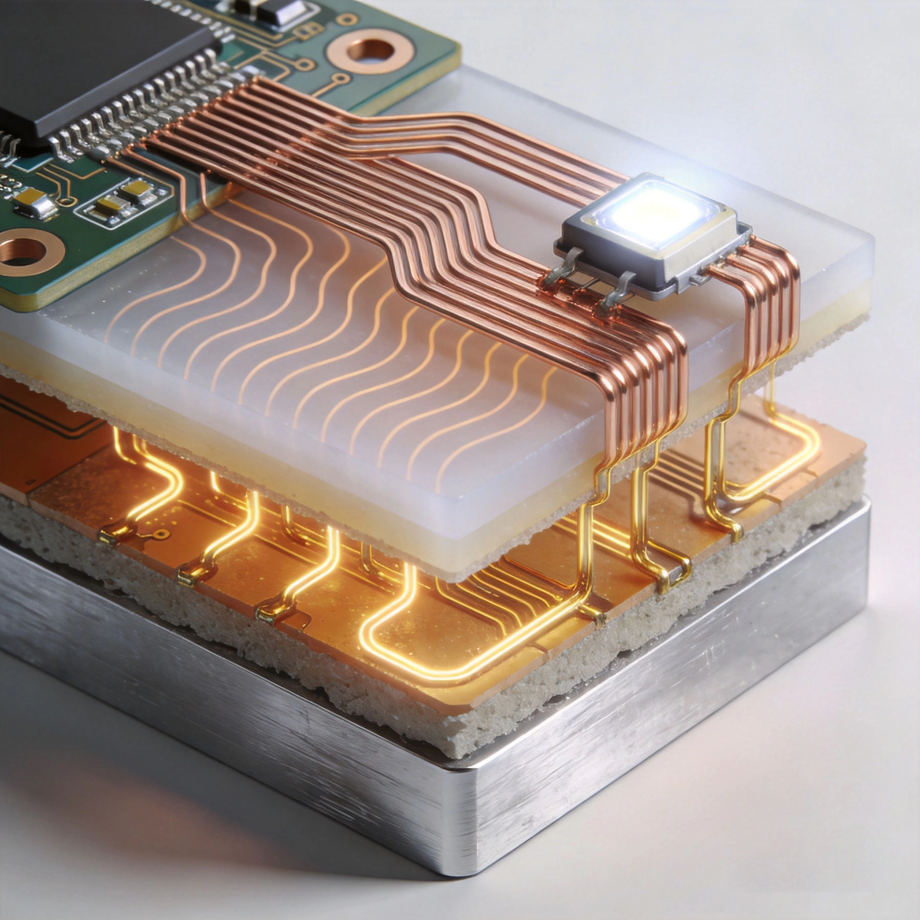
Unlike standard PCBs that use organic materials like fiberglass and epoxy resin as substrate, MCPCBs feature a three-layer composite structure optimized for thermal performance:
This construction creates a vertical heat transfer path: heat generated by components on the copper layer flows through the dielectric layer into the metal core, where it dissipates across the large surface area. The metal core can then transfer heat to external heatsinks or radiate it directly into the environment.
The thermal advantages of MCPCBs become apparent when comparing them to traditional Pcb Materials:
This dramatic difference—over 400× better thermal conductivity for aluminum core PCBs—translates directly into lower component operating temperatures, improved reliability, and enhanced performance for thermal-critical devices.
Aluminum represents the most widely used metal core material due to its optimal balance of properties:
Common aluminum alloys include 5052 (good formability) and 6061 (high strength), selected based on application-specific requirements. Aluminum core PCBs dominate the LED lighting market and find widespread use in power electronics where thermal management is critical but extreme thermal performance isn't required.
Copper core PCBs provide the highest thermal performance available for MCPCB technology:
Copper core PCBs excel in applications requiring maximum thermal performance, such as high-power LED arrays, power converters, and RF amplifiers where thermal budgets are extremely tight. The weight penalty and higher cost limit use to applications where thermal performance outweighs these disadvantages.
Advanced MCPCB designs incorporate composite materials that optimize thermal performance while addressing specific application requirements:
These specialized configurations address niche requirements that standard aluminum or copper core PCBs cannot meet, typically for aerospace, military, or cutting-edge commercial applications.
LED technology exemplifies the need for MCPCBs. While LEDs convert only 15-25% of electrical energy to light, the remaining 75-85% becomes heat that must be managed effectively. MCPCBs have become the standard PCB choice for LED applications across all market segments:
In LED applications, MCPCBs typically integrate directly with heatsinks. The metal core contacts external thermal interfaces, providing efficient heat transfer paths that maintain LED junction temperatures within specified ranges. This thermal management directly impacts LED efficiency, color consistency, and operational lifespan.
Power conversion equipment generates significant heat that must be managed to ensure reliable operation. MCPCBs provide the thermal performance that power electronics applications demand:
In power electronics applications, MCPCBs often serve as heat spreaders for power semiconductor devices. The metal core directly contacts heatsinks or thermal interfaces, providing low thermal resistance paths that prevent device thermal derating and maximize power density.
Automotive environments present extreme thermal challenges. Underhood temperatures can reach 150°C, while exterior lighting systems face thermal cycling from -40°C to +125°C. MCPCBs address these challenges through:
Automotive applications include LED lighting systems, powertrain control modules, battery management systems, and sensor interface electronics where thermal management is critical.
High-frequency power amplifiers generate substantial heat that must be managed to maintain performance. Copper core MCPCBs provide the thermal performance that RF applications require while offering potential electrical ground plane benefits:
In RF applications, MCPCBs must balance thermal requirements with electrical performance. Dielectric material selection becomes critical to maintain dielectric constant stability while providing thermal conductivity.
The dielectric layer between copper circuitry and metal core represents a critical design parameter. This layer must:
Common dielectric materials include epoxy-based compounds filled with ceramic materials (aluminum oxide, boron nitride) to enhance thermal conductivity while maintaining electrical insulation. Thermal conductivity typically ranges from 1-3 W/m·K, with higher values providing better thermal performance at increased cost.
Effective MCPCB deployment requires careful attention to thermal interfaces beyond the board itself:
Thermal via arrays represent a particularly effective design technique. By placing arrays of vias under hot components, designers create direct thermal paths through the dielectric layer into the metal core, bypassing the dielectric's thermal resistance limitation.
While MCPCBs excel thermally, electrical isolation requires careful design attention:
Designers must verify that dielectric materials meet both thermal and electrical requirements simultaneously. Higher thermal conductivity dielectrics often have lower electrical breakdown voltages, creating trade-offs that require careful material selection.
MCPCB manufacturing differs from standard PCB processes in several important ways:
These process differences mean that not all PCB manufacturers offer MCPCB capabilities. Manufacturers specializing in MCPCBs invest in specialized equipment and process controls necessary for consistent quality.
MCPCBs typically cost 2-4× more than equivalent FR-4 boards, depending on:
While this cost premium appears significant, the total cost of ownership analysis often justifies MCPCB deployment in thermal-critical applications.
Temperature accelerates virtually all failure mechanisms in electronics. Components operating at elevated temperatures fail faster than those maintained within specified ranges. MCPCBs reduce operating temperatures, which translates directly into:
These reliability benefits often offset the initial cost premium through reduced field failures and extended product lifecycles.
Beyond reliability, MCPCBs provide performance benefits that enable competitive advantages:
These performance advantages can enable product differentiation that justifies MCPCB deployment costs through market positioning and premium pricing opportunities.
Metal core PCBs represent specialized technology designed specifically for applications where thermal management determines success or failure. By providing thermal conductivity hundreds of times greater than traditional PCB materials, MCPCBs enable reliable operation of high-power LEDs, power electronics, automotive systems, and RF applications that would struggle with conventional PCB technology.
Understanding when to deploy MCPCB technology requires evaluating thermal requirements against cost considerations. Not every application benefits from MCPCB deployment, but for thermal-critical designs, MCPCBs provide capabilities that simply cannot be achieved with traditional PCB materials. The initial cost premium pays dividends in reliability, performance, and market competitiveness for applications where thermal management determines product viability.
As electronic systems continue advancing toward higher power densities and more compact form factors, MCPCB technology will become increasingly important. Engineers who understand MCPCB capabilities and implementation best practices position themselves to design products that succeed in demanding thermal environments where traditional PCB materials fall short.
Aluminum core PCBs offer thermal conductivity of 150-170 W/m·K at relatively low cost and light weight. Copper core PCBs provide 380-400 W/m·K thermal conductivity but cost 2-3× more and are significantly heavier. Choose aluminum for cost-sensitive applications with moderate thermal requirements. Use copper for extreme thermal performance requirements where cost and weight are secondary considerations.
Yes, MCPCBs can be fabricated with multiple copper layers, though practical limits apply due to thermal path lengths. Common configurations include single-sided boards with components on one side or double-sided designs with components on both sides. Very complex multi-layer designs typically use hybrid approaches with metal core combined with traditional PCB sections.
Thermal expansion differences create stress that can cause delamination or cracking. MCPCB designers address this through careful material selection, controlled dielectric thickness, and proper via design. Manufacturers use qualified dielectric materials specifically engineered for thermal expansion matching with metal cores to ensure reliability across temperature ranges.
Yes, but dielectric material selection becomes critical. MCPCBs for RF applications use specialized dielectric materials with stable dielectric constants across frequency and temperature. Copper core MCPCBs often serve RF applications better due to superior thermal performance and potential ground plane benefits, but dielectric properties must be carefully selected for each frequency band.
Thermal performance verification typically includes thermal imaging under load, thermal resistance measurements between components and ambient environment, and thermal cycling testing to verify long-term reliability. Many applications require dielectric breakdown voltage testing and insulation resistance verification to ensure electrical isolation meets specifications.
Heavy Copper PCBs: The Solution for High-Current Industrial ApplicationsJune/18/2026
End-to-End Industrial PCB Solutions: From Design to DeliveryJuly/08/2026
An Introduction to HDI Technology for Compact Industrial ElectronicsJune/16/2026
Custom Industrial PCB Solutions for the Automotive SectorMay/27/2026
Manufacturing Challenges in 20+ Layer Industrial PCB SolutionsJuly/09/2026
Tailored Industrial PCB Solutions for Medical Device ManufacturersJune/12/2026
Design Guidelines for Durable Flex PCB Solutions in Dynamic ApplicationsJuly/10/2026
Why Choose Rigid-Flex PCB Solutions for Complex Industrial Assemblies?June/17/2026