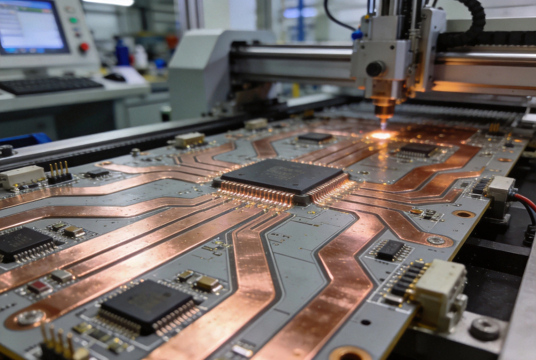
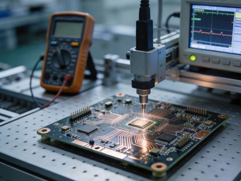
Industrial Power Electronics demand printed circuit boards capable of handling extraordinary current levels. From electric vehicle charging stations and renewable energy inverters to industrial motor drives and welding equipment, these applications require PCBs with copper weights far exceeding standard consumer electronics. Extreme heavy copper PCBs—those with copper weights from 10 oz to 40 oz or more—represent a specialized manufacturing discipline that combines advanced plating technology, precision etching processes, and innovative Thermal Management techniques.
Unlike conventional PCBs that use 1 oz or 2 oz copper, extreme heavy copper boards must manage hundreds of amperes while maintaining reliability under harsh operating conditions. The manufacturing processes for these specialized boards differ significantly from standard PCB Fabrication, requiring specialized equipment, modified chemical processes, and deep engineering expertise. This comprehensive guide explores the complete manufacturing journey of extreme heavy copper PCBs from raw laminate to finished product.

Understanding Extreme Heavy Copper Requirements
Defining Heavy Copper Categories
The PCB industry categorizes copper weights according to application requirements:
-
Standard copper – 0.5 oz to 2 oz (17-70 μm), typical for consumer electronics
-
Heavy copper – 3 oz to 10 oz (105-350 μm), industrial and automotive applications
-
Extreme heavy copper – 10 oz to 40+ oz (350-1400+ μm), Power Electronics and industrial systems
Each category requires progressively more specialized manufacturing capabilities. Extreme heavy copper fabrication pushes the boundaries of conventional PCB technology, demanding innovative approaches at every process step.
Applications Driving Extreme Heavy Copper Demand
Several industrial sectors rely on extreme heavy copper PCBs:
-
Power conversion – Inverters, rectifiers, and DC-DC converters handling high currents
-
Electric vehicle infrastructure – Fast charging stations requiring 200A+ capacity
-
Renewable energy – Solar inverters and wind turbine power electronics
-
Industrial Automation – Motor drives and welding equipment
-
Medical equipment – MRI systems and high-power laser drivers
-
Defense and aerospace – Radar systems and high-reliability Power Distribution
Material Selection and Preparation
Base Laminate Requirements
Extreme heavy copper PCBs start with specialized base materials capable of withstanding the thermal and mechanical stresses of thick copper processing:
-
High Tg laminates – Glass transition temperatures of 170°C or higher prevent resin softening during Thermal Cycling
-
Low CTE materials – Minimizing coefficient of thermal expansion mismatch between copper and substrate reduces stress
-
Enhanced Thermal Conductivity – Aluminum-based or thermally conductive laminates for applications requiring heat spreading
-
Thick core materials – Substrates ranging from 1.6mm to 3.2mm or thicker to accommodate deep copper features
Popular materials include high-performance FR-4 variants, polyimide for high-temperature applications, and metal-core substrates for Thermal Management.
Copper Foil Selection
The starting Copper Foil must support the final copper thickness requirements:
-
Standard electrodeposited foil – Starting point for plated heavy copper structures
-
High-tensile foil – Improved Mechanical Strength for thick copper applications
-
Very low profile (Vlp) foil – Smooth surface for fine pattern etching even with thick copper
-
Rolled annealed copper – For applications requiring maximum ductility and Thermal Conductivity
Advanced Plating Processes
Electroless Copper Deposition
Before electrolytic plating can begin, the through-holes and surface must receive a thin conductive layer:
-
Hole conditioning – Chemical treatment ensuring hole wall adhesion
-
Catalyst application – Depositing palladium nucleation sites
-
Electroless copper – Auto-catalytic deposition of 0.5-1.0 μm copper layer
-
Quality verification – Confirming continuity and adhesion
This initial layer provides the conductivity necessary for subsequent electrolytic plating.
Pattern Plating Technology
The heart of extreme heavy copper manufacturing lies in advanced electrolytic plating:
-
High-throw chemistry – Specialized electrolytes providing uniform deposition in high-aspect-ratio holes
-
Pulse plating – Periodic reverse current improving via fill and surface distribution
-
High-current density operation – Accelerated deposition rates for thick copper buildup
-
Temperature control – Maintaining optimal bath temperature for consistent plating quality
Building 20 oz copper might require 20-30 hours of plating time, compared to 30 minutes for standard 1 oz copper.
Via Filling and Planarization
Extreme heavy copper PCBs often use filled vias for reliability and thermal performance:
-
Conductive via fill – Copper or conductive epoxy filling Thermal Vias
-
Non-conductive fill – Epoxy filling for signal vias in thick copper boards
-
Planarization grinding – Removing excess fill material to create flat surface
-
Sequential plating – Multiple plating cycles to achieve target thickness with uniform distribution
Precision Etching Challenges
The Etching Dilemma
Etching thick copper presents fundamental challenges:
-
Extended etch times – Removing 20 oz copper takes significantly longer than 1 oz
-
Undercut control – Lateral etching beneath resist creates trapezoidal trace profiles
-
Feature definition – Maintaining fine line resolution with thick copper
-
Etch uniformity – Ensuring consistent removal across large board areas
Standard etching processes designed for thin copper cannot simply be extended for heavy copper applications.
Advanced Etching Techniques
Specialized etching processes address thick copper requirements:
-
Step etching – Multiple etch cycles with resist reinforcement between steps
-
High-pressure spray etching – Improved chemistry replenishment at the etch front
-
Regenerated chemistry – Continuously refreshed etchant maintaining consistent activity
-
Optimized resist systems – Thicker, more durable photoresists capable of withstanding extended etch times
Controlled Etch Factor
Managing the relationship between vertical and lateral etching is critical:
-
Etch factor calculation – Ratio of vertical etch depth to lateral undercut
-
Compensated artwork – Design adjustments accounting for expected undercut
-
Process characterization – Establishing etch factors for specific copper thicknesses
-
Quality verification – Cross-sectional analysis confirming trace geometry
Typical etch factors for extreme heavy copper range from 2:1 to 4:1, significantly lower than the 5:1 or better achievable with standard copper.
Multilayer Construction Techniques
Layer Stackup Design
Multilayer heavy copper boards require carefully engineered stackups:
-
Symmetrical construction – Balanced copper distribution preventing warpage
-
Sequential Lamination – Building thick copper layers separately before final assembly
-
Hybrid constructions – Combining heavy copper power layers with standard copper signal layers
-
Thermal Via integration – Strategic placement of Thermal Vias connecting heat-generating areas to cooling surfaces
Pressing and Lamination
Laminating heavy copper layers requires modified processes:
-
Extended press cycles – Longer times ensuring complete resin flow around thick copper features
-
Higher pressures – Compensating for reduced flow capability with thick copper
-
Prepreg selection – High-flow materials capable of filling gaps around heavy copper
-
Vacuum lamination – Removing trapped air preventing voids
Thick copper layers create significant topography that standard lamination processes struggle to accommodate.
Mechanical Processing Considerations
Drilling Challenges
Creating holes in extreme heavy copper presents unique difficulties:
-
Extended drill times – Penetrating thick copper requires slower feed rates
-
Tool wear – Abrasive copper accelerates drill bit degradation
-
Heat generation – Friction heat can smear resin and damage hole quality
-
Aspect ratio limitations – Thick copper reduces achievable aspect ratios
Specialized drilling equipment with enhanced cooling and tool management systems addresses these challenges.
Routing and Profiling
Separating individual boards from panels requires adapted approaches:
-
Enhanced cutting tools – Robust routers capable of cutting through thick copper edges
-
Reduced cutting speeds – Slower feeds preventing tool breakage and edge damage
-
Tab routing design – Stronger retention tabs necessary for heavy boards
-
Edge quality requirements – Smooth edges for safety and dimensional tolerance
Thermal Management Integration
Metal Core and IMS Technologies
For applications requiring exceptional Heat Dissipation:
-
Aluminum core PCBs – Metal substrate providing heat spreading
-
Copper core PCBs – Superior thermal conductivity for extreme applications
-
Insulated Metal Substrates (IMS) – Thin Dielectric Layer over metal base
-
Direct Bond Copper (DBC) – Ceramic substrate with bonded Copper Foil for high-voltage, high-thermal applications
Embedded Copper Technologies
Advanced techniques integrate massive copper into PCB structures:
-
Embedded bus bars – Solid copper conductors laminated within the board
-
Copper coin insertion – Press-fit copper slugs for localized heat spreading
-
Press-fit terminals – Heavy copper connections for external wiring
-
Thick copper planes – Internal layers with 10-20 oz copper for current distribution
Surface Finishes for Heavy Copper
Hot Air Solder Leveling (HASL)
Traditional HASL faces limitations with extreme heavy copper:
-
Thermal mass challenges – Thick copper requires extended heating
-
Solder coating uniformity – Difficulty achieving consistent thickness
-
Thermal stress – High temperatures can stress thick copper boards
-
Process modifications – Extended preheating and controlled cooling
Alternative Finishes
More suitable finishes for heavy copper applications:
-
Electroless Nickel Immersion Gold (ENIG) – Uniform coating regardless of copper thickness
-
Immersion Silver – Cost-effective alternative with good solderability
-
Organic Solderability Preservatives (OSP) – Thin, economical protection for soldering
-
Electrolytic Nickel/Gold – Hard gold for edge connectors requiring wear resistance
Quality Assurance and Testing
Electrical Testing Challenges
Verifying extreme heavy copper PCBs requires adapted approaches:
-
High-current testing – Verifying Current Carrying Capacity under load
-
Micro-ohm measurements – Detecting high-resistance connections
-
Dielectric withstanding voltage – High-pot testing for insulation integrity
-
Insulation resistance – Verifying adequate isolation between conductors
Thermal Validation
Ensuring thermal performance meets specifications:
-
Thermal imaging – Identifying hot spots during operation
-
Current loading tests – Actual high-current validation of trace capacity
-
Thermal Cycling – Verifying reliability through repeated temperature excursions
-
Cross-sectional analysis – Microscopic examination of copper quality and geometry
Cross-Sectional Analysis
Microscopic examination reveals critical quality characteristics:
-
Copper thickness verification – Confirming achieved plating thickness
-
Via quality assessment – Examining plating integrity in holes
-
Trace geometry – Measuring actual versus designed dimensions
-
Delamination detection – Identifying layer separation or voids
Assembly Considerations
Component Mounting Challenges
Assembling components on extreme heavy copper boards presents unique issues:
-
Thermal mass during soldering – Thick copper requires extended heating profiles
-
Component compatibility – Ensuring components can withstand thermal exposure
-
Pad preparation – Achieving solderable surfaces on thick copper
-
Reflow profile optimization – Extended soak and reflow zones
Heavy Component Support
Industrial components often have significant mass:
-
Mechanical reinforcement – Additional mounting hardware for heavy components
-
Staking and bonding – Adhesive support for vibration resistance
-
Strain Relief – Managing mechanical stress on connections
-
Threaded inserts – Metal threaded holes for secure mechanical attachment
Cost and Lead Time Factors
Manufacturing Cost Drivers
Extreme heavy copper PCBs command premium pricing due to:
-
Extended processing times – Plating and etching take hours rather than minutes
-
Specialized equipment – Heavy-duty plating tanks and etching systems
-
Material costs – High copper content and specialized laminates
-
Lower yields – Higher defect rates during processing
-
Skilled labor requirements – Experienced technicians for process control
Lead Time Considerations
Manufacturing timelines extend significantly for extreme heavy copper:
-
Standard PCBs – 5-10 days typical
-
Heavy copper (3-6 oz) – 2-3 weeks
-
Extreme heavy copper (10+ oz) – 4-6 weeks or longer
-
Complex multilayers – Additional time for sequential processing
Planning for these extended lead times is essential for project scheduling.
Conclusion
Manufacturing extreme heavy copper PCBs represents one of the most challenging specialties in printed Circuit Board Fabrication. The combination of thick copper processing, precision patterning, and thermal management creates a manufacturing environment where standard processes fail and innovative approaches become essential.
Success in extreme heavy copper manufacturing requires specialized equipment, modified chemical processes, and deep engineering expertise developed through years of focused experience. The manufacturers who excel in this space have invested heavily in capabilities that few possess, creating significant barriers to entry but also substantial value for industrial customers who need reliable high-current solutions.
As Industrial Electronics continue pushing power densities higher and reliability requirements more stringent, the demand for extreme heavy copper PCBs will only grow. Understanding these manufacturing processes helps designers create products that leverage these advanced capabilities effectively, ultimately delivering power electronics systems that meet the demanding requirements of modern industrial applications.
Extreme Heavy Copper PCB Manufacturing
Our facility specializes in heavy copper PCBs up to 40 oz copper weight, serving industrial power electronics, EV charging, and renewable energy applications. With advanced plating capabilities and rigorous Quality Control, we deliver reliable high-current solutions for the most demanding applications. Contact us to discuss your extreme heavy copper requirements.
Frequently Asked Questions
What is the maximum copper weight available for PCBs?
Specialized manufacturers can produce PCBs with copper weights up to 40 oz (1.4 mm) or even thicker in specific configurations. Beyond this, designers often transition to bus bars or embedded copper technologies integrated with standard PCBs.
How does thick copper affect PCB cost?
Extreme heavy copper PCBs typically cost 3-10x more than standard boards due to extended processing times, specialized equipment requirements, and lower manufacturing yields. However, they eliminate the need for separate bus bars and connectors, often reducing overall system cost.
What are the minimum trace and space capabilities with heavy copper?
Trace width and spacing requirements increase with copper thickness due to etching undercut. With 10 oz copper, minimum trace widths are typically 0.5 mm or greater. Fine features require selective plating or step-etching processes.
Can heavy copper PCBs have multiple layers?
Yes, multilayer heavy copper PCBs are common, though layer count and copper thickness combinations are limited by lamination challenges. Hybrid constructions combining heavy copper power layers with standard signal layers are particularly popular.
How do you test heavy copper PCBs for current capacity?
Current capacity is validated through high-current testing with actual loads, thermal imaging to identify hot spots, and cross-sectional analysis to verify copper thickness and geometry. Many manufacturers also perform thermal cycling to ensure reliability.