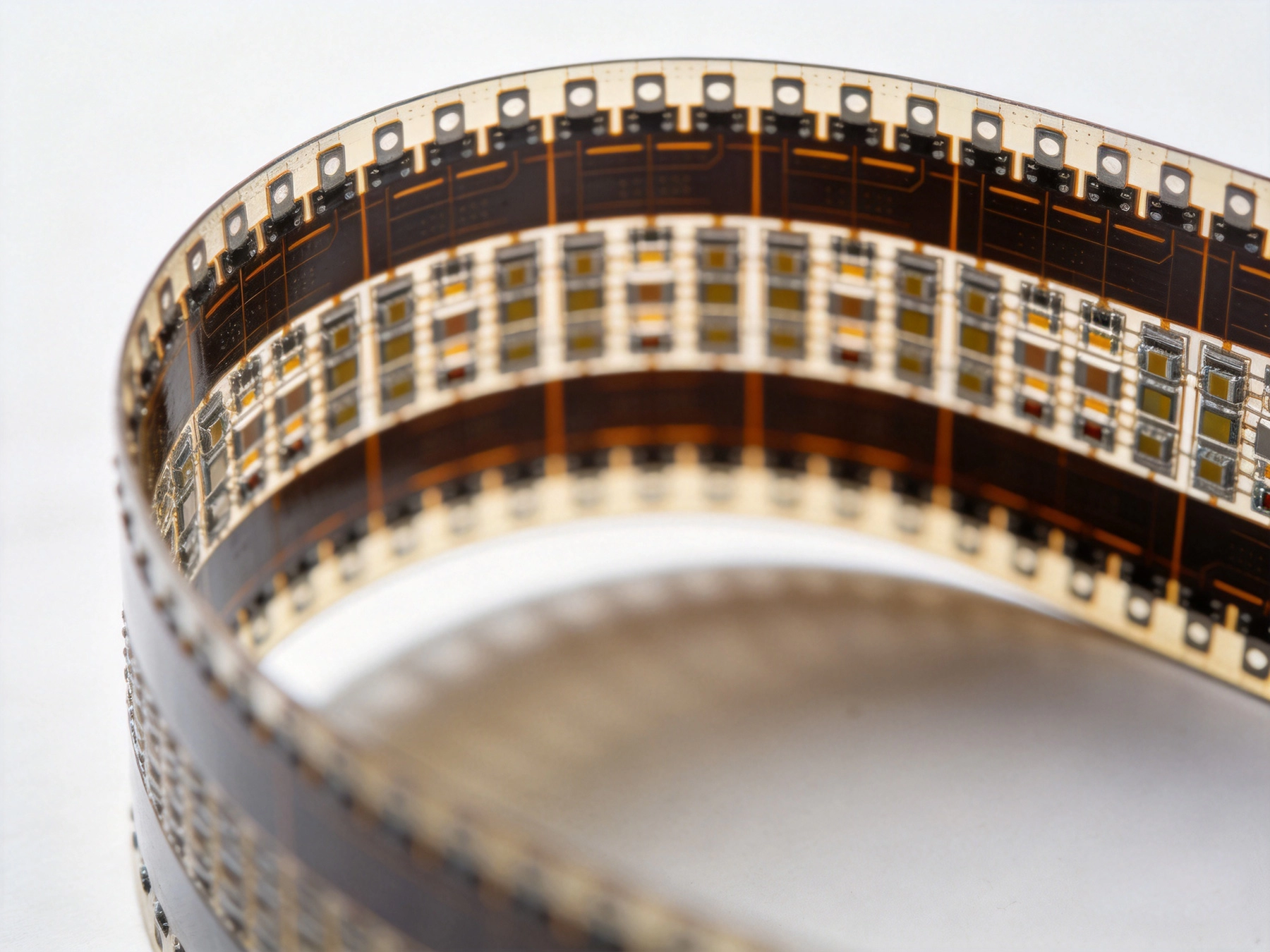
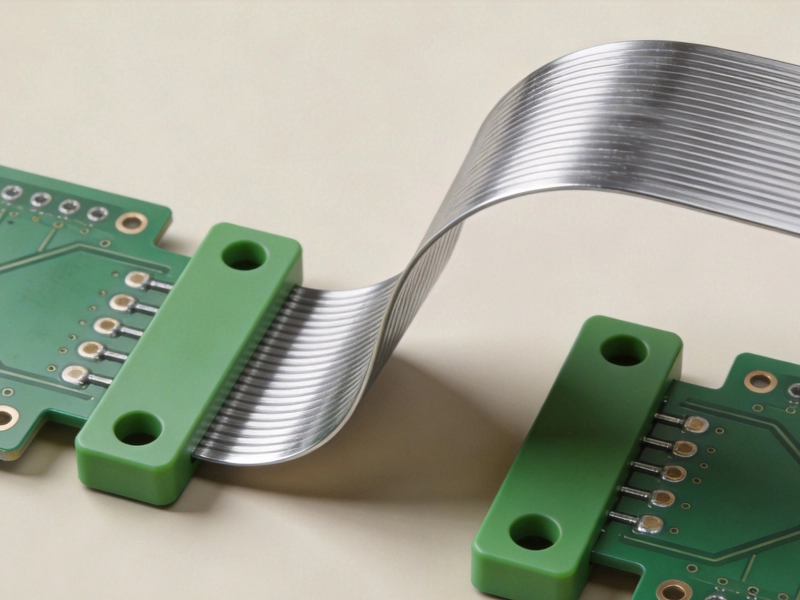
Flexible printed circuit boards have revolutionized Electronics Design by enabling three-dimensional packaging, reduced weight, and improved reliability in dynamic applications. However, one of the most critical challenges engineers face when working with flex PCB solutions is properly managing Bend Radius requirements. Understanding and overcoming Bend Radius challenges is essential for creating reliable Flexible Circuits that can withstand repeated flexing without failure.
The bend radius—the minimum radius a flexible circuit can bend without damaging the copper traces or dielectric material—directly impacts the mechanical reliability, electrical performance, and overall lifespan of flexible PCBs. Get this wrong, and you risk cracked traces, Delamination, and catastrophic failure in the field. Get it right, and you unlock the full potential of flexible electronics for applications ranging from wearable devices to aerospace systems.
This comprehensive guide explores the fundamentals of bend radius in flexible PCBs, common challenges engineers encounter, and proven strategies for overcoming these challenges to create robust, reliable flex circuit solutions.

Understanding Bend Radius Fundamentals
Before diving into challenges and solutions, it's essential to understand what bend radius means in the context of flexible PCBs and the factors that influence it.
What is Bend Radius?
Bend radius refers to the minimum radius at which a flexible circuit can be bent without causing damage to the conductors or dielectric materials. It's typically measured from the centerline of the bend to the inner surface of the flex circuit. The bend radius is a critical design parameter that determines how tightly a flex circuit can be folded or curved during both assembly and operation.
There are two types of bend scenarios to consider:
- Static bend: A one-time bend during installation, after which the circuit remains in that position. Static bends can tolerate tighter radii because the stress isn't repeated.
- Dynamic bend: Repeated bending during normal operation, such as in a hinge or moving mechanism. Dynamic bends require significantly larger bend radii to withstand the cumulative stress of repeated flexing cycles.
Key Factors Affecting Bend Radius
Several factors influence the minimum bend radius a flexible circuit can accommodate:
- Copper thickness: Thicker copper requires larger bend radii because it's less flexible and more prone to fatigue cracking.
- Dielectric material: Different flex materials have different flexibility characteristics. Polyimide is generally more flexible than polyester.
- Number of layers: Multi-layer flex circuits generally require larger bend radii than single or double-sided circuits.
- Plating: Electroplated copper is less flexible than rolled annealed copper, affecting bend radius requirements.
- Component placement: Components near the bend area create stress concentrations that may require larger bend radii.
- Operating environment: Temperature extremes and humidity can affect material properties and bend requirements.
Industry Standards and Guidelines
Ipc Standards provide guidelines for bend radius based on circuit construction and application:
- Single-sided flex: Minimum bend radius typically 3-6 times the total circuit thickness
- Double-sided flex: Minimum bend radius typically 6-10 times the total circuit thickness
- Multi-layer flex: Minimum bend radius typically 10-15 times the total circuit thickness
- Dynamic flexing: Requires 2-3x larger bend radius than static applications
Common Bend Radius Challenges
Engineers encounter several predictable challenges when working with bend radius requirements in flexible Pcb Design. Understanding these challenges is the first step toward developing effective solutions.
Space Constraints vs. Bend Requirements
One of the most common conflicts occurs when the available space for bending is smaller than the required bend radius. This is particularly challenging in compact devices where every millimeter counts. Engineers must balance the need for tight packaging with the mechanical requirements for reliable flexing.
Example scenario: A wearable device requires the flex circuit to wrap around a 3mm radius battery compartment, but the circuit design requires a minimum 6mm bend radius based on its construction.
Trace Cracking and Fatigue
Repeated flexing causes copper traces to experience mechanical stress that can lead to fatigue cracking. This is especially problematic with:
- Electroplated copper, which is more brittle than rolled annealed copper
- Thicker copper traces (2oz and above)
- Sharp corners in trace routing
- Traces perpendicular to the bend direction
Fatigue cracks typically develop gradually and may not cause immediate failure, but they can lead to intermittent connections and eventual catastrophic failure.
Delamination and Layer Separation
In multi-layer flex circuits, the different layers experience different amounts of stress during bending. The outer layers experience tensile stress while inner layers experience compressive stress. This stress differential can cause:
- Delamination between copper and dielectric layers
- Separation of adhesive layers in adhesive-based constructions
- Cracking of the dielectric material itself
These issues are particularly problematic in dynamic flexing applications where repeated stress cycles accumulate damage over time.
Component Damage Near Bends
Placing components too close to bend areas creates several problems:
- Mechanical stress transferred to components can cause solder joint failure
- Component bodies can create stress concentrations in the flex circuit
- Tall components can physically interfere with the bending process
- Thermal expansion differences between components and flex materials can create additional stress
Even surface-mount components can create problems if they're located in areas that experience significant bending stress.
Impedance Control Challenges
Bending Flexible Circuits can affect Controlled Impedance traces, particularly in high-frequency applications:
- Changes in trace geometry due to bending can alter impedance
- Dielectric Constant changes under stress can affect signal propagation
- Coupling between adjacent traces may vary with bend radius
These effects are usually minimal but can be significant in high-speed or RF applications.
Design Strategies for Overcoming Bend Radius Challenges
Effective design strategies can help overcome bend radius challenges while maintaining circuit functionality and reliability.
Optimized Layer Stackup Design
Careful layer stackup design can significantly improve bend radius performance:
- Neutral axis placement: Position critical traces near the neutral axis where stress is minimal during bending. The neutral axis is typically at the center of the stackup.
- Balanced construction: Use symmetrical layer stackups to distribute stress evenly across the circuit.
- Adhesive-less laminates: Use adhesive-less polyimide constructions for better flexibility and reduced delamination risk.
- Thinner materials: Specify thinner dielectric and copper materials where possible to reduce overall circuit thickness.
- Material Selection: Choose high-elongation copper (rolled annealed) for bend areas.
Intelligent Trace Routing
Smart trace routing can dramatically improve Flex Circuit Reliability:
- Parallel routing: Route traces parallel to the bend direction rather than perpendicular. Traces running parallel to the bend experience significantly less stress.
- Curved traces: Use curved traces instead of 90-degree corners, especially in bend areas. Curves distribute stress more evenly.
- Staggered traces: Avoid aligning multiple traces in the same bend area to distribute stress across a wider region.
- Wider traces: Use wider traces for critical signals in bend areas. Wider traces distribute stress over a larger area and are less prone to fatigue.
- Reduced copper weight: Use 1oz or 0.5oz copper in bend areas rather than heavier copper weights.
Bend Area Optimization
Special design techniques for bend areas:
- Removed dielectric: Remove dielectric material in bend areas to reduce thickness and improve flexibility. This is particularly effective for single-sided flex.
- Stiffeners: Add stiffeners away from bend areas to create controlled bend points and protect vulnerable areas.
- Stress relief patterns: Implement stress relief patterns or cutouts in bend areas to reduce stress concentrations.
- Gradual transitions: Use gradual transitions between stiff and flexible areas rather than abrupt changes.
Component Placement Strategies
Smart component placement prevents bend-related failures:
- Keep-out zones: Establish clear keep-out zones around bend areas where no components are placed.
- Component orientation: Orient long components parallel to the bend direction when placement near bends is unavoidable.
- Strain Relief: Use Strain Relief features such as bends or loops in the flex circuit before component areas.
- Low-profile components: Use low-profile components in areas near bends to reduce stress concentrations.
- Adhesive mounting: Consider adhesive mounting for components near bend areas to reduce mechanical stress on solder joints.
Material Selection for Improved Flexibility
Choosing the right materials is fundamental to overcoming bend radius challenges. Different materials offer varying degrees of flexibility and fatigue resistance.
Copper Types and Characteristics
The type of copper used significantly impacts bend radius performance:
- Rolled Annealed (RA) Copper: Most flexible option with excellent fatigue resistance. Grain structure is aligned in the rolling direction, providing superior performance in dynamic flexing applications. Preferred for critical bend areas.
- Electrodeposited (ED) Copper: Less expensive but more brittle than RA copper. Random grain structure makes it less suitable for dynamic flexing. Can be used in non-critical areas or static bend applications.
- High-elongation copper: Special alloys with elongation values exceeding 20%. Excellent for demanding flex applications but more expensive.
Dielectric Material Options
Dielectric materials vary in flexibility and performance characteristics:
- Polyimide: Industry standard for flexible circuits. Excellent thermal stability, Chemical Resistance, and mechanical properties. Available in various thicknesses from 12.5μm to 125μm.
- Polyester (PET): Lower cost alternative with good flexibility but limited temperature resistance (typically <125°C). Suitable for less demanding applications.
- PEN (Polyethylene Naphthalate): Offers better temperature resistance than PET while maintaining good flexibility. Intermediate performance and cost.
- PTFE: Excellent electrical properties and temperature resistance but more challenging to process. Used in high-frequency flex applications.
Adhesive vs. Adhesive-less Constructions
The choice between adhesive-based and adhesive-less constructions affects flexibility:
- Adhesive-based: Traditional construction using acrylic or epoxy adhesives. Generally thicker and less flexible. More prone to delamination in dynamic flexing applications.
- Adhesive-less: Direct bonding of copper to polyimide without adhesive layers. Thinner, more flexible, and better for dynamic flexing. Higher cost but superior performance.
- Cast adhesive: Newer technology that provides a thinner, more uniform adhesive layer than traditional laminated adhesives. Good middle-ground option.
Advanced Manufacturing Techniques
Advanced manufacturing techniques can help overcome bend radius challenges that are difficult to address through design alone.
Laser Processing for Precision Features
Laser technology enables precise feature creation that improves flex performance:
- Laser skiving: Precise removal of dielectric material to create thinner bend areas or controlled stiffness transitions.
- Laser drilling: Creation of micro-vias and small holes with minimal thermal damage to surrounding materials.
- Laser cutting: Precise outline cutting with smooth edges that reduce stress concentrations.
- Laser ablation: Selective material removal for creating stress relief patterns and features.
Specialized Plating Processes
Plating techniques can improve flexibility in specific areas:
- Selective plating: Apply thicker plating only in areas where needed, leaving bend areas with thinner, more flexible copper.
- Soft gold plating: Use soft gold deposits (hardness < 90 Knoop) for flexing areas to maintain flexibility.
- Pulse plating: Use pulse plating processes that create more ductile copper deposits with better fatigue resistance.
Forming and Bending Processes
Specialized forming processes can achieve tight bends while maintaining reliability:
- Pre-forming: Pre-form flex circuits to the required bend radius before assembly to reduce stress during installation.
- Controlled radius tooling: Use precision tooling to ensure consistent bend radius during assembly.
- Gradual forming: Implement multi-step forming processes that gradually achieve the final bend radius.
- Heat-assisted forming: Use controlled heat during forming to improve material compliance and reduce spring-back.
Testing and Validation Approaches
Rigorous testing and validation are essential for ensuring flex circuits will meet bend radius requirements in real-world applications.
Mechanical Testing Methods
Standard mechanical tests evaluate flex circuit durability:
- Bend radius testing: Systematic testing at various bend radii to identify the minimum safe radius for the specific design.
- Flex cycle testing: Repeated flexing cycles (typically 10,000 to 100,000 cycles) to simulate dynamic flexing conditions.
- Tensile testing: Measurement of tensile strength and elongation to understand material behavior under stress.
- Peel strength testing: Evaluation of copper-to-dielectric adhesion strength.
Electrical Testing During Flexing
Electrical testing during flexing identifies reliability issues:
- Continuity monitoring: Continuous monitoring of trace continuity during flex cycle testing.
- Impedance measurement: Measurement of Controlled Impedance traces in various bend states.
- Resistance monitoring: Tracking resistance changes that may indicate developing cracks or delamination.
- Insulation resistance testing: Verification of insulation integrity after flexing.
Environmental Testing
Environmental factors can affect flex circuit performance:
- Temperature cycling: Testing across the operating temperature range to identify thermal-mechanical interactions.
- Humidity testing: Exposure to high humidity conditions to evaluate moisture effects on flexibility.
- Combined stress testing: Simultaneous application of mechanical and environmental stresses for realistic evaluation.
Application-Specific Considerations
Different applications have unique bend radius requirements and challenges.
Wearable Electronics
Wearable devices present specific flex circuit challenges:
- Body conformity: Circuits must conform to curved body surfaces with varying radii.
- Dynamic flexing: Constant movement requires excellent fatigue resistance.
- Comfort requirements: Thin, flexible circuits are essential for user comfort.
- Moisture exposure: Sweat and environmental moisture require protective considerations.
Automotive Applications
Automotive flex circuits face demanding conditions:
- Temperature extremes: Operation from -40°C to +125°C or higher.
- Vibration and shock: Constant mechanical stress from vehicle operation.
- Chemical exposure: Exposure to automotive fluids and cleaning agents.
- Long-term reliability: Requirements for 10-15 year service life.
Medical Devices
Medical applications have unique requirements:
- Biocompatibility: Materials must meet medical device standards.
- Sterilization compatibility: Must withstand repeated sterilization cycles.
- Reliability: Critical function demands exceptional reliability.
- Small size: Miniaturization requirements drive tight bend radii.
Aerospace and Defense
Aerospace applications demand maximum reliability:
- Extreme environments: Operation in vacuum, radiation, and temperature extremes.
- Long life requirements: 20+ year operational life in some applications.
- Vibration and shock: Launch and operational environments create severe mechanical stress.
- Weight constraints: Lightweight design is critical.
Cost vs. Performance Trade-offs
Understanding the cost implications of various bend radius solutions helps in making informed design decisions.
Material Cost Considerations
Material choices significantly impact cost:
- Rolled annealed copper: 20-30% more expensive than electrodeposited copper.
- Adhesive-less laminates: 40-60% more expensive than adhesive-based constructions.
- High-elongation copper: 50-100% premium over standard copper.
- Specialty dielectrics: PTFE and other specialty materials can cost 2-5x more than standard polyimide.
Processing Cost Impacts
Advanced processing adds cost:
- Laser processing: Adds 15-25% to processing costs.
- Selective plating: Requires additional tooling and process steps.
- Pre-forming operations: Additional assembly step increases cost.
- Enhanced testing: Comprehensive testing adds 10-20% to total cost.
Cost Optimization Strategies
Balance performance requirements with cost constraints:
- Targeted Material Selection: Use premium materials only in critical bend areas.
- Design optimization: Good design reduces the need for expensive materials and processes.
- Volume considerations: Higher volumes can justify investments in better materials and processes.
- Life-cycle cost analysis: Consider total cost of ownership, not just initial manufacturing cost.
Future Trends in Flexible Circuit Technology
Emerging technologies are expanding the possibilities for flexible circuits and bend radius performance.
Stretchable Electronics
New technologies enable circuits that can stretch significantly:
- Elastic substrates: Materials that can stretch 20-100% while maintaining electrical continuity.
- Wavy metal traces: Pre-formed wavy traces that can stretch and compress.
- Liquid metal conductors: Gallium-based alloys that remain conductive under extreme deformation.
3D Printing of Flexible Circuits
Additive manufacturing enables new design possibilities:
- Direct printing: Printing conductive traces directly onto flexible substrates.
- 3D structures: Creating three-dimensional flexible circuit structures.
- Rapid prototyping: Faster iteration cycles for flex circuit design.
Advanced Materials
New materials improve flexibility and performance:
- Graphene-based materials: Exceptional electrical and mechanical properties.
- Nanocomposite dielectrics: Enhanced properties through nanoparticle reinforcement.
- Bio-based materials: Sustainable alternatives with good flexibility characteristics.
Conclusion
Overcoming bend radius challenges in flexible PCB solutions requires a comprehensive approach that combines thoughtful design, appropriate material selection, advanced manufacturing techniques, and thorough testing. While the challenges are significant, the solutions are well-understood and proven through countless successful applications across diverse industries.
The key to success lies in understanding the specific requirements of your application, selecting appropriate materials and construction methods, implementing smart design practices, and validating performance through comprehensive testing. When these elements come together, flexible PCBs can deliver remarkable reliability even in demanding dynamic flexing applications.
As flexible circuit technology continues to evolve, new materials, processes, and design techniques will further expand the possibilities for overcoming bend radius challenges. Staying current with these developments while maintaining a solid foundation in fundamental flex circuit design principles positions engineers to create increasingly sophisticated and reliable flexible electronic solutions.
The investment in proper bend radius design and validation pays dividends in product reliability, customer satisfaction, and reduced warranty costs—making it one of the most important considerations in flexible PCB development.
Frequently Asked Questions
Q: What happens if I bend a flex circuit tighter than its minimum bend radius?
A: Bending tighter than the minimum bend radius can cause immediate damage such as cracked traces, delamination, or dielectric failure. Even if it works initially, the circuit will likely fail prematurely due to accumulated damage from over-stressed materials.
Q: Can I improve bend radius after the circuit is manufactured?
A: Generally no—bend radius is determined by the materials and construction used during manufacturing. However, post-processing techniques like laser skiving can remove material in specific areas to improve local flexibility.
Q: How do I calculate the minimum bend radius for my flex circuit?
A: Start with IPC guidelines (3-6x thickness for single-sided, 6-10x for double-sided, 10-15x for multi-layer), then adjust based on copper type, plating, and application (static vs. dynamic). Always validate through testing.
Q: Is rolled annealed copper always better than electrodeposited copper?
A: Not always—rolled annealed copper is better for flexing areas and dynamic applications, but electrodeposited copper is suitable for static bends and non-critical areas at lower cost. Many designs use both types strategically.
Q: How many flex cycles can a typical flex circuit withstand?
A: It varies dramatically based on design and construction. Simple single-sided circuits might withstand 100,000+ cycles, while complex multi-layer circuits may be limited to 1,000-10,000 cycles. Proper design and material selection are key to achieving desired cycle life.