Open Nav


Renewable energy systems demand electronics that operate reliably in demanding environments while maximizing energy conversion efficiency. From solar inverters converting DC to grid-compatible AC to wind turbine control systems managing blade pitch and yaw, printed circuit boards form the electronic backbone of sustainable power generation. Designing and manufacturing PCBs for these applications requires specialized approaches that address Thermal Management, power density, and long-term reliability requirements beyond standard commercial electronics.
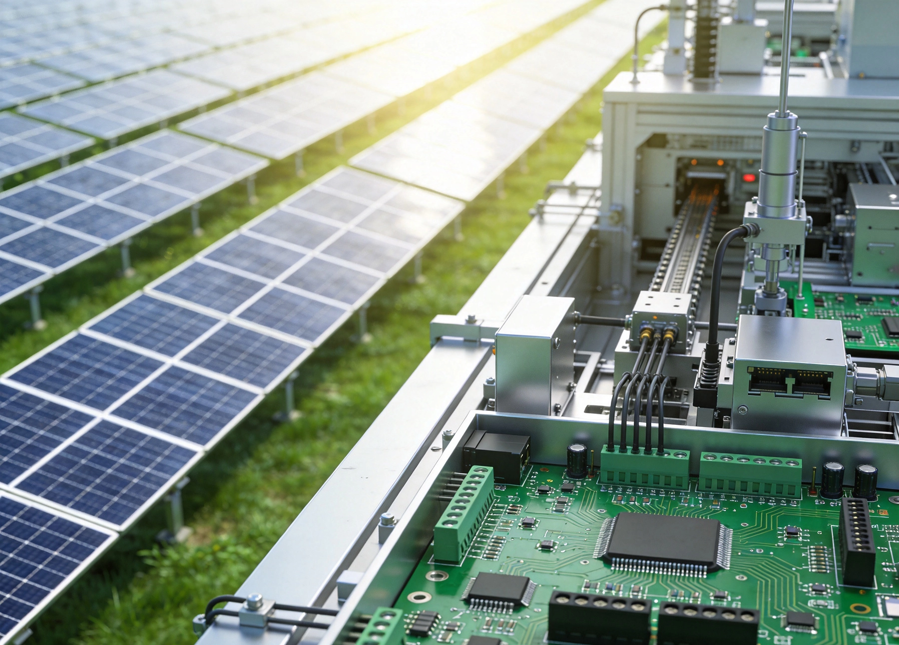
Renewable energy systems present environmental and operational challenges that differ significantly from typical industrial or consumer applications. Understanding these challenges guides Pcb Design decisions and manufacturing requirements.
Thermal Cycling affects all outdoor renewable energy installations. Solar inverters experience daily temperature swings from frigid overnight conditions to intense midday heat. Wind turbines encounter similar variations plus mechanical vibration from blade rotation. These thermal cycles stress solder joints, vias, and component packages, demanding designs that accommodate differential expansion across materials with varying coefficients of thermal expansion.
High humidity environments particularly affect coastal and offshore wind installations. Salt-laden air accelerates corrosion of unprotected metals and can degrade PCB insulation resistance over time. Enclosure design, Conformal Coating selection, and material choices must address moisture exposure throughout system lifetime.
Power conversion efficiency directly impacts renewable energy system economics. Every percentage point of conversion efficiency translates into additional energy harvest and faster return on investment. Pcb Design directly affects efficiency through trace resistance, switching losses, and Thermal Management that prevents efficiency-reducing temperature rise.
Long service life requirements often span 20-25 years for renewable energy installations. Consumer electronics product cycles of 3-5 years bear no relation to infrastructure expectations. Components must be selected for long-term availability, and manufacturing processes must ensure reliability throughout demanding operational lives.
Solar inverters convert the DC output from photovoltaic panels into grid-compatible AC power. This power conversion process demands PCBs optimized for high current handling, thermal performance, and switching efficiency.
High-current traces in solar inverters must handle tens to hundreds of amperes while minimizing resistive losses. Heavy copper boards with 2-4 oz copper or specialized heavy copper constructions provide the current-carrying capacity these applications demand. Trace width calculations must account for temperature rise, not just current capacity.
DC bus bars often replace conventional traces for the highest current paths. These Thick Copper structures provide low-resistance Power Distribution while serving as heat spreading elements. PCB manufacturers offer specialized capabilities for incorporating bus bars into board designs.
Thermal Vias beneath power semiconductors transfer heat from devices to internal planes or external heat sinks. Via arrays with thermal clearance and proper plating ensure reliable heat extraction without creating manufacturing defects.
Isolation requirements between high-voltage DC inputs and low-voltage control circuits demand careful spacing, slotting, and Material Selection. Creepage and clearance distances must meet relevant safety standards for photovoltaic applications.
Signal Integrity in inverter control circuits affects switching precision and overall efficiency. Gate drive signals for IGBTs and MOSFETs require Controlled Impedance traces and minimal ringing to achieve clean switching transitions.
Communication interfaces including Ethernet, RS-485, and wireless modules enable monitoring and control of inverter systems. These circuits typically follow standard PCB practices but must interface reliably with harsh electromagnetic environments created by power switching.
Microcontroller and DSP circuits handling power conversion algorithms demand careful decoupling, grounding, and layout to maintain measurement accuracy and control loop stability.
Wind turbines require sophisticated control systems managing blade pitch, yaw orientation, and power conversion. These applications present vibration challenges alongside thermal and humidity concerns.
Motor driver PCBs in pitch control systems must operate reliably while subjected to constant mechanical vibration. Solder Joint Reliability under vibration stress requires attention to component selection, mounting methods, and potentially adhesive reinforcement for critical components.
Position sensing circuits providing feedback on blade angle require noise immunity and reliability. These circuits often use resolvers or encoders with analog signal conditioning requiring careful shielding and filtering.
Redundancy requirements in safety-critical pitch control systems demand duplicated circuitry with fail-safe operation. PCBs supporting redundant designs require careful partitioning and physical separation to ensure single-point failures cannot affect both channels.
Central processing boards in wind turbine nacelles aggregate sensor data, execute control algorithms, and manage communication with grid operators and SCADA systems. These boards combine processing power with robust interfaces requiring ESD protection and filtering.
Power supply design for turbine controllers must accommodate wide input voltage ranges from turbine generators, with transient suppression protecting sensitive electronics from voltage spikes during grid disturbances.
Environmental sealing considerations affect PCB design when controllers are located in non-pressurized nacelle environments. Conformal Coating or potting provides moisture and contaminant protection while requiring compatibility with components and thermal management needs.
Battery energy storage systems (BESS) buffer renewable energy for dispatch during peak demand or when generation is unavailable. These systems require PCBs managing high currents, precise battery monitoring, and grid interconnection.
Cell monitoring circuits measure individual cell voltages and temperatures across large battery strings. High accuracy measurement circuits require careful analog layout, referencing, and noise isolation to achieve the precision necessary for balancing and protection.
Balancing circuits distribute charge current to equalize cell states of charge, extending battery pack life. These circuits must handle substantial power while maintaining measurement accuracy across temperature extremes.
Isolation barriers between battery string voltages reaching hundreds or thousands of volts and low-voltage control electronics demand specialized design approaches. Optocouplers, digital isolators, and transformer-coupled interfaces provide galvanic isolation while passing control and measurement signals.
DC-DC converter PCBs interface battery strings with inverter stages, requiring similar thermal and current-handling considerations as solar inverter power stages. Bidirectional power flow demands designs accommodating current in both directions.
Grid-tie inverter PCBs for storage systems must meet similar requirements to solar inverters while managing complex power flow scenarios involving simultaneous charging, discharging, and grid support functions.
Material Selection for renewable energy PCBs extends beyond standard FR-4 to address specific environmental and performance requirements.
Metal core PCBs with aluminum or copper substrates provide direct thermal paths from components to the metal backing. These constructions excel for high-powerdensity applications where conventional thermal management proves inadequate.
High-Tg laminates with glass transition temperatures exceeding 170°C provide thermal stability during demanding operating conditions. Standard FR-4 materials may not survive the thermal extremes experienced in solar installations or offshore environments.
Ceramic substrates including aluminum nitride and alumina offer excellent Thermal Conductivity alongside Dielectric Strength. These materials suit the most demanding Power Electronics applications but command significant cost premiums.
Polyimide laminates provide enhanced Thermal Resistance and mechanical flexibility compared to standard materials. These benefits prove valuable in applications with Thermal Cycling or mechanical stress requirements.
halogen-free materials increasingly specified for environmental compliance, though these materials require careful process adjustments compared to standard FR-4 formulations.
Conformal coating materials including acrylics, urethanes, and silicones provide moisture and contamination protection for harsh environment applications. Material selection must consider Thermal Conductivity impact, flexibility, and rework compatibility.
Producing PCBs for renewable energy applications requires manufacturing discipline exceeding standard commercial requirements. These additional controls ensure reliability throughout extended service lives.
Solder paste inspection (SPI) before component placement identifies printing defects that might create field reliability issues. Consistent paste volume and registration prevent cold joints and other defects that thermal cycling might exacerbate.
Reflow profile optimization for high-thermal-mass boards ensures complete solder wetting while preventing damage to temperature-sensitive components. Profiling across representative boards validates process parameters for production runs.
Conformal coating application requires controlled thickness, complete coverage, and masking of contacts and connectors. Automated coating systems provide consistency difficult to achieve with manual application.
Ict and Flying Probe Testing verifies component placement and solder joint integrity before Functional Testing. These electrical tests catch defects that might pass visual inspection but cause field failures.
Functional Testing under load conditions validates inverter and converter operation before shipment. Testing at rated power validates thermal performance while burn-in testing identifies early-life failures.
Environmental Stress Screening including temperature cycling and vibration testing accelerates failure mechanisms that might otherwise appear during field operation. Screening levels depend on application criticality and customer requirements.
Designing PCBs for 20+ year reliability requires systematic attention to failure mechanisms and margin optimization.
Component derating based on actual operating conditions rather than datasheet ratings extends component life. Power semiconductor junction temperatures should maintain substantial margin below maximum ratings.
Thermal simulation during design phase predicts operating temperatures and identifies hotspots before prototype testing. Software tools enable virtual prototyping of thermal performance.
Thermal relief design balances heat spreading through planes against solderability of plated through-hole components. Improper thermal relief creates solder defects or poor thermal connections.
Vibration mitigation for wind turbine applications includes component orientation, adhesive reinforcement, and potentially mechanical isolation. Design guidelines specific to vibration environments address component stress during operation.
Expansion accommodation through flexible circuit designs, strain reliefs, and appropriate clearances prevents fatigue failures from differential expansion across temperature cycles.
Connector selection for field-serviceable systems must withstand repeated mating cycles while maintaining reliable contact. Industrial-grade connectors exceed consumer specifications for cycling and environmental exposure.
While renewable energy systems justify quality investments, cost optimization remains important for competitive system pricing and market adoption.
Standardization of board sizes and layer counts across product families reduces fabrication costs through panel optimization and process specialization.
Component pooling across product variations reduces inventory costs and improves availability. Selecting components with multiple sourcing options protects against supply disruptions.
Design For Manufacturing (DFM) collaboration with PCB manufacturers identifies cost reduction opportunities early in development when changes cost least.
Panel efficiency
improves through optimized array design that maximizes boards per fabrication panel. Engineering charges amortize across higher board counts, reducing per-unit costs.Process selection matching capabilities to requirements avoids over-specification. Not every board needs gold plating or HDI construction when standard finishes and constructions satisfy application requirements.
Volume forecasting enables manufacturers to plan capacity and offer pricing reflecting committed volumes. Early capacity reservations protect lead times while potentially securing better pricing.
Selecting manufacturing partners for renewable energy applications requires evaluating capabilities beyond standard commercial Electronics Manufacturing.
Heavy copper capabilities demonstrate ability to handle high-current designs. Verify maximum copper weight, registration accuracy, and plating quality for Thick Copper constructions.
Thermal management expertise including Metal Core Pcb capability, Thermal Via expertise, and thermal simulation support indicates qualification for Power Electronics applications.
Environmental Testing capability including temperature cycling, HALT/HASS, and vibration testing enables comprehensive qualification without external laboratory dependencies.
Quality certifications including ISO 9001 and industry-specific standards demonstrate systematic quality management. Automotive Iatf 16949 or medical ISO 13485 requirements may apply depending on application.
Process documentation including work instructions, inspection criteria, and change control procedures ensures consistency across production runs and engineering changes.
Traceability systems tracking component lots, production dates, and inspection results enable Failure Analysis and customer compliance documentation.
Component lifecycle management becomes critical for products with 20-year service expectations. Partners must understand Component Obsolescence risks and actively manage long-term availability.
Engineering support capacity for design changes, failure investigation, and Continuous Improvement requires dedicated resources beyond production operations.
Geographic considerations affect logistics, communication, and potentially tariff implications. Evaluate whether partner locations align with your supply chain requirements.
Renewable energy systems demand PCBs engineered for demanding environmental conditions, high reliability over extended service lives, and optimized efficiency for economic operation. From solar inverters to wind turbine controls to energy storage systems, each application presents unique requirements driving specialized design and manufacturing approaches.
Material selection, thermal management, and manufacturing process controls require attention beyond standard commercial practices. Heavy copper designs, high-Tg laminates, and conformal coating address environmental challenges while specialized testing and qualification ensure field reliability.
Partner selection for renewable energy PCBs should emphasize experience with power electronics applications, quality systems ensuring long-term consistency, and commitment to supporting products throughout extended lifecycles. The right manufacturing partner becomes a strategic asset enabling competitive renewable energy systems.
Investment in appropriate PCB solutions for renewable energy applications pays returns through system reliability, efficiency optimization, and reduced lifecycle costs. As renewable energy continues growing as a percentage of global electricity generation, quality Electronics Manufacturing partners enable the transition to sustainable power.
Solar inverter power stage PCBs typically use 2-4 oz copper for main current paths, with some designs incorporating specialized heavy copper constructions up to 6 oz or higher. Control circuits and signal layers generally use standard 1 oz copper. The specific weight depends on current levels, acceptable temperature rise, and efficiency targets.
Renewable energy PCBs typically require higher thermal management capability, enhanced environmental resistance for outdoor deployment, extended reliability for 20+ year service life, and optimization for power conversion efficiency. Standard Industrial Electronics may operate in controlled environments with shorter lifecycle expectations.
Offshore wind applications demand robust Moisture Protection given salt-laden environments. Urethane conformal coatings provide excellent moisture barrier properties and Chemical Resistance. Acrylic coatings offer good protection with easier rework capability. Material selection should consider temperature range, flexibility requirements, and application method compatibility.
Qualification timelines vary based on application criticality and testing requirements. Basic electrical and Environmental Testing might complete in 4-8 weeks. Comprehensive qualification including Accelerated Life Testing, vibration testing, and field validation might require 3-6 months. Working with manufacturers experienced in renewable energy applications accelerates qualification through proven processes.
Many manufacturers offer NPI (new product introduction) services optimized for prototypes alongside production lines optimized for volume. Prototype services typically accept longer lead times for lower volumes, while production services offer faster cycles at higher volumes. Selecting manufacturers offering both capabilities simplifies Supply Chain Management across product lifecycles.
An Introduction to HDI Technology for Compact Industrial ElectronicsJune/16/2026
Rogers vs. PTFE: Comparing Materials for High-Frequency SolutionsSeptember/17/2026
End-to-End Industrial PCB Solutions: From Design to DeliveryJuly/08/2026
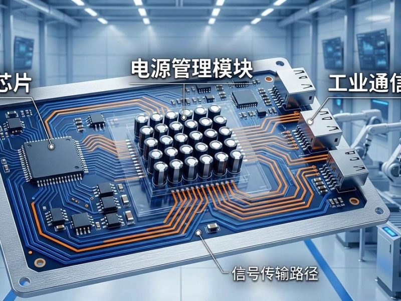
Unlocking Performance with High-Layer Count Industrial PCB SolutionsJune/15/2026
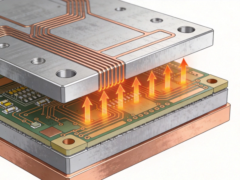
Aluminum vs. Copper Base: Choosing the Best Metal Core SolutionJuly/29/2026
Rapid Prototyping Services: Fast-Tracking Your Industrial PCB SolutionsSeptember/30/2026
Via-in-Pad and Microvias: Key Features of Advanced HDI SolutionsJuly/26/2026

Cost Analysis: Is Rigid-Flex the Right Solution for Your Industrial Project?September/15/2026