Open Nav


Every PCB that ships with an undetected defect carries a hidden cost that compounds over time. A board that fails in the factory burns assembly time and materials. A board that fails at customer site generates warranty claims, support overhead, and reputation damage that no one budgeted for. The difference between these outcomes often traces back to design decisions made long before the first component was placed—decisions about testability.
Design for Testability sounds like a manufacturing concern, and it is. But DFT isn't just about what happens at the test station. It's about building quality into the product from the earliest design stages, making defects findable before they find your customers. In industrial applications where failure consequences range from production downtime to safety incidents, DFT becomes less of a best practice and more of a survival requirement.

When a board fails test, engineers instinctively blame the manufacturing process. Sometimes that's correct—the assembly line made an error, a component proved defective, or a process parameter drifted out of specification. But more often, the root cause traces back to the design itself. Components placed too close together prevent probe access. Ground planes without clearance block measurement points. Microprocessor-based designs without boundary scan capability hide failures under populated packages that no physical probe can reach.
These aren't manufacturing problems. They're design problems that manufacturing discovers too late. By the time a DFT deficiency surfaces during test, the board is built. The options are limited: work around the untestable area with indirect measurements, accept reduced test coverage, or redesign the board. All three options cost time and money that better upfront design could have prevented.
The compounding nature of late DFT discovery makes it expensive. If a test coverage gap appears in prototype, it might delay the program by a few weeks while the team redesigns. If it appears in production, the delay multiplies across every unit affected until a corrective action propagates through the supply chain. Discovering DFT gaps after production commitment can cost more than the original design engineering.
Test coverage—the percentage of potential defects that your test process can detect—directly determines the defect escape rate that reaches your customers. A test covering 85% of potential defects will let roughly 15% of defects through to customers. For consumer products with forgiving failure modes and low repair costs, that escape rate might be acceptable. For industrial equipment, the consequences of escaped defects are orders of magnitude higher.
Mathematical models for defect detection illustrate the stakes clearly. If your manufacturing process produces 2% defective boards, and your test coverage is 90%, your customer defect rate is 0.2%. That sounds acceptable until you ship a million boards and 2,000 customers receive defective products. Improving test coverage to 99% reduces customer defects to 200—better, but still significant for high-consequence applications.
The cost of improving test coverage must be weighed against the cost of escaped defects. Adding comprehensive boundary scan test vectors costs engineering time but no hardware cost. Building bed-of-nails fixtures for in-circuit testing adds $10,000-30,000 per board revision. Flying Probe Testing avoids fixture cost but runs slower and provides less coverage. Functional test development can rival NRE costs for complex products. The right investment level depends on your defect consequences, production volume, and product margins.
Physical test access requires Test Points—dedicated pads sized and spaced for probe contact. A test point isn't just a piece of exposed copper. It's a deliberate design decision about how manufacturing will verify your product, and it must be planned as early as any other feature on the board.
Minimum test point size matters for reliable probe contact. Test probes range from 0.015" to 0.040" diameter, with 0.020" (1mm) being common for standard applications. Smaller probes exist but wear faster and require more precise fixture alignment. Design Test Points at least 0.030" diameter to accommodate standard probes without requiring precision alignment equipment.
Test point spacing affects fixture complexity and cost. Standard fixtures assume 0.100" minimum center-to-center spacing between adjacent test points. Tighter spacing is possible but requires custom spring probes and precision-machined fixture plates that increase cost dramatically. When density forces tight spacing, communicate the requirement to your test engineering team early so fixture design can accommodate it.
Every critical node needs a test point. In practice, this means power rails, ground references, signal inputs and outputs, and any node where a defect would produce a detectable failure. Untestable nodes—buried in ground planes, under component bodies, or inaccessible through probe contact—create coverage gaps that defects exploit. The discipline is identifying every node that must be verified and ensuring each has accessible test point before the layout is finalized.
Boundary scan changed the DFT equation for complex digital designs. When devices support IEEE 1149.1 JTAG boundary scan, signals at the device pins can be controlled and observed through the scan chain without physical probe access. This is critical for area-array packages like BGAs and QFNs where physical probing of interior pins is simply impossible.
For JTAG to provide useful test coverage, multiple conditions must be met. Your devices must include boundary scan capability—not all ICs do. Your design must include the required JTAG infrastructure: TDI, TDO, TMS, TCK, and optional TRST signals routed appropriately, plus pull-ups or pull-downs on control signals. Your test vectors must be generated to exercise the boundary scan chain in ways that detect manufacturing defects.
The strategic value of boundary scan extends beyond board-level testing. Chain integrity testing verifies that all boundary scan devices are properly connected. Interconnect testing uses boundary scan cells to verify signal continuity between devices without requiring physical access to the net. Cluster testing can verify some non-scan devices by controlling and monitoring their interface signals through adjacent scan-capable devices.
Designing for JTAG requires allocating board space for the connector, routing the dedicated signals, and including the test access port in your design rules. These requirements add small cost in layout time and board space but provide disproportionate test coverage improvement for complex digital boards. Budget the engineering time to define your JTAG strategy during schematic design, not after layout is complete.
In-circuit testing (ICT) uses a bed-of-nails fixture to contact multiple test points simultaneously, applying power and stimulus while measuring responses at hundreds of nodes per second. ICT provides high coverage of manufacturing defects: missing components, wrong parts, solder opens, solder bridges, and many component value verification checks. For boards with sufficient test point density, ICT achieves coverage levels that no other single test method matches.
Fixture cost is the main barrier to ICT adoption for low-volume or prototype production. A basic bed-of-nails fixture for a moderate-complexity board costs $8,000-15,000. Complex boards with hundreds of test points, mixed technologies, or unusual form factors can exceed $30,000. These costs amortize across production volume, making ICT economical for high-volume production but expensive for prototypes and low-volume builds.
Design decisions directly affect fixture feasibility. Boards must be flat enough to seat properly against the fixture probe plate. Warped boards create unreliable contacts that generate false failures. Panelization must accommodate fixture alignment features. And test point placement must match the fixture design assumptions—typically 0.100" minimum pitch, minimum 0.030" pad diameter, and adequate clearance around pads for probe access.
ICT can't test what it can't reach. Analog circuits with no DC test points at accessible nodes will not be verified electrically. Microcontroller functionality requires firmware to be loaded before ICT can test the programmed behavior. RF performance requires specialized test equipment beyond standard ICT capability. These limitations aren't failures of ICT—they're design requirements that need test strategies beyond ICT coverage.
Flying Probe Testing addresses the fixture cost problem by using movable probe heads instead of fixed nail beds. The machine moves probes to each test point in sequence, contacting pads directly without requiring a dedicated fixture. Setup cost is minimal since there's no fixture to manufacture, and the same test station handles any board that fits within its size envelope.
The tradeoff is speed and coverage. Flying probe testing runs dramatically slower than ICT—a test that takes seconds on a bed-of-nails fixture might take minutes with flying probes. For 100-unit prototype runs, the time difference is tolerable. For 10,000-unit production runs, the economics flip toward fixture-based ICT. Flying probe also has more limited analog test capability compared to ICT, since flying probe instruments are typically less sophisticated than dedicated ICT analog measurement hardware.
Design requirements for flying probe are less stringent than for ICT since there's no fixture to accommodate. Test points can be smaller, spacing can be tighter, and panelized boards don't require special features for probe access. This flexibility makes flying probe the natural choice for prototype verification, low-volume production, and engineering validation testing where quick turns matter more than high throughput.
The strategic approach for many products uses flying probe during development and prototype phases, then transitions to ICT for production once volume justifies fixture investment. The flying probe results during development validate the test coverage assumptions, so the ICT fixture design starts from validated requirements rather than theoretical calculations.
Functional test verifies that the assembled board does what it's supposed to do—not just that individual components are present and soldered correctly, but that the system functions as designed. A board might pass ICT perfectly yet fail to initialize because of an incorrect oscillator frequency or a firmware defect. Functional test catches these system-level failures that component-level testing misses.
Functional test strategy should be defined during system architecture, not during manufacturing planning. The test points and interfaces required for functional verification must be designed into the product. External connectors for communication, programming, and monitoring provide test access. Internal test points for power rails, reset signals, and critical nodes enable troubleshooting when functional test fails.
Design for functional test access means including programming interfaces in your design. JTAG/SWD debug connectors for microcontroller programming, UART or JTAG test points for serial communication, and LED or indicator access for visual confirmation all support efficient functional verification. Without these interfaces, functional test requires custom test jigs, longer test times, and more engineering involvement for each board tested.
Built-in self-test (BIST) capabilities reduce external test requirements. When the product's firmware can verify its own components—RAM test, flash verification, peripheral functionality—the external test system becomes simpler and faster. BIST adds development cost but reduces manufacturing test time and improves fault isolation. The investment pays back across production volume in reduced test labor and improved defect detection.
Automated Optical Inspection (AOI) catches visual defects that electrical testing misses. Solder defects, component placement errors, polarity reversals, and foreign material contamination all show up visually but may not create electrical failures detectable by probe-based testing. AOI bridges this gap with camera-based inspection systems that compare boards against golden reference images.
AOI effectiveness depends on design choices that affect inspectability. Component spacing must provide resolution for the inspection camera to capture clear images. Shadowing from tall components can hide defects under adjacent parts. Color-coded components require inspection systems calibrated for the specific color palette. Board warpage creates focus problems that reduce inspection reliability.
Designing for AOI means providing clear sight lines for inspection cameras. Minimum clearances around components based on your AOI equipment's resolution should be specified in your design rules. 3D AOI systems handle some of the shadowing problems that 2D systems struggle with, but at higher cost and longer cycle time. Choose your AOI strategy based on the defect modes most likely in your manufacturing process and the inspection equipment available.
Some defects hide completely beneath component packages where no optical inspection can reach. BGA solder joints, QFN bottom-side terminations, and buried vias are invisible to external inspection. X-ray Inspection penetrates these packages to reveal internal defects: voiding in solder joints, alignment problems, cracked joints, and insufficient solder volume.
2D X-ray imaging projects the entire assembly into a single image, making interpretation difficult for complex multilayer structures. 3D X-ray CT (computed tomography) reconstructs the assembly into slice images that isolate specific layers, providing unambiguous defect identification at the cost of longer scan times and higher equipment investment.
Design factors that affect X-ray Inspection effectiveness include package materials and thickness. Plastic packages attenuate X-rays less than ceramic, making inspection easier. Lead-based solder is more radiopaque than lead-free, which can make lead-free inspection more challenging. The specific defect modes in your assembly process should drive X-ray inspection strategy—if your main failure modes are detectable through AOI or ICT, X-ray may be unnecessary. If BGA attachment is critical and defect consequences are high, X-ray becomes essential.
Placing test points on the bottom side of the board seems like space optimization but creates fixture complexity and alignment challenges. Test points belong on the primary assembly side—the same side as the components—where probe access is straightforward and fixture design is simpler.
Using net names instead of physical designators for test point documentation creates confusion when the design changes. A test point documented as "Net00047" instead of "R12-Pad1" becomes impossible to locate after the net is renamed during design cleanup. Use physical pad references or coordinate-based documentation that survives design iteration.
Assuming test engineering will work around poor test access is a mistake that surfaces late in programs. Test engineering involvement should start during schematic design, not after layout is complete. By the time test engineering sees the layout, the component placement and routing decisions that determine testability are already made—and changing them means going back through layout iteration.
Skipping test coverage validation against actual defects costs more than it saves. Every design change that affects test access should trigger a test coverage review. If your test coverage drops without compensating changes elsewhere, you're accepting higher defect escape rates without realizing it.
Design for Testability isn't a manufacturing checkbox—it's a fundamental aspect of product development that determines whether your quality investment pays off or leaks away through escaped defects. The design decisions that enable good test coverage—test point placement, JTAG infrastructure, AOI accessibility, functional test interfaces—are small additions to the overall design effort but provide disproportionate returns in manufacturing yield and field reliability.
Starting DFT planning during system architecture, before component selection and layout begin, ensures that test access requirements influence design choices rather than constraining them after decisions are made. Test engineers and design engineers working together from the beginning produce better results than either group working in isolation.
The cost of comprehensive test coverage is real but bounded. The cost of escaped defects is unbounded—warranty claims, customer relationships, reputation, liability exposure. For industrial applications where failure consequences are high, the economic case for DFT investment is clear. Design it in from the beginning, and your manufacturing process can deliver the quality your customers expect.
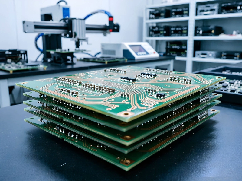
How to Avoid Costly Mistakes with Proper Industrial PCB DFMJuly/03/2026

Panelization Strategies for Efficient Industrial PCB Design and AssemblySeptember/08/2026
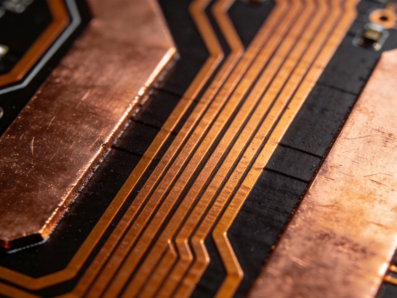
Design Rules for Heavy Copper Traces in Power ElectronicsJuly/27/2026
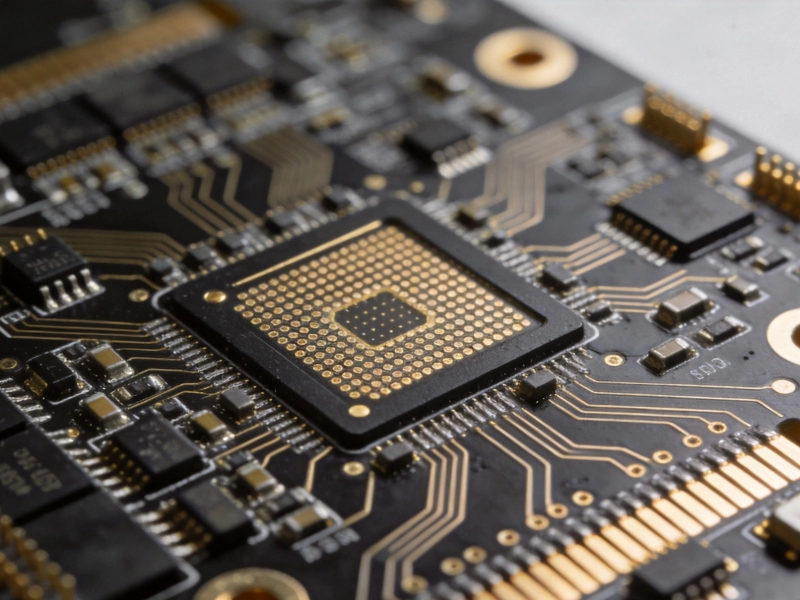
Cost vs. Performance: When to Use HDI Solutions in Industrial DesignSeptember/14/2026
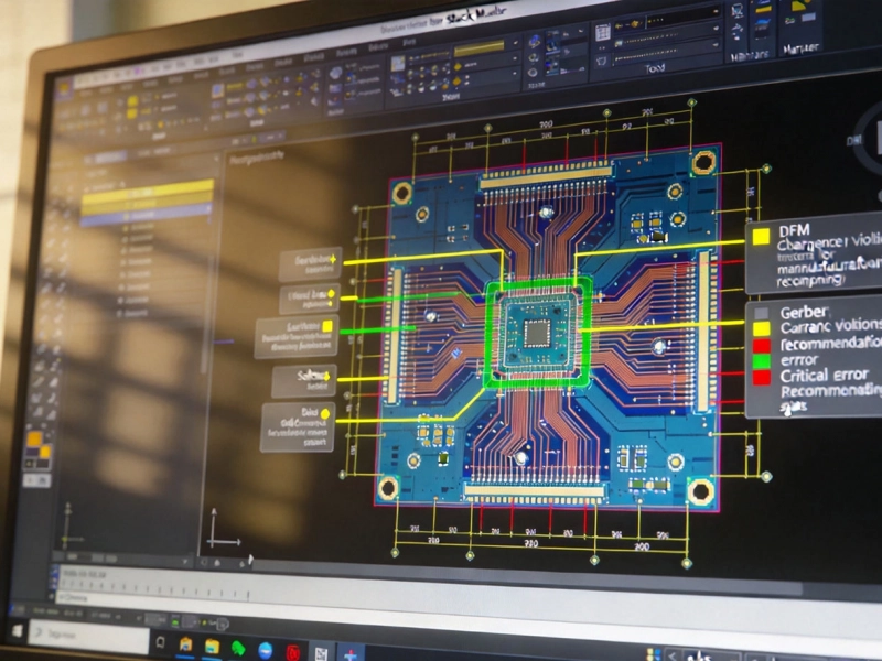
Essential Rules for Industrial PCB DesignMay/27/2026

Essential Rules for Industrial PCB DesignJune/08/2026
Designing for 10+ Years of Operation: The Industrial PCB Reliability GuideOctober/16/2026

Optimizing Trace Width and Spacing in Industrial PCB DFMAugust/06/2026