Open Nav


Industrial Pcb reliability determines the uptime, maintenance costs, and operational success of equipment across manufacturing, energy, transportation, and infrastructure sectors. When circuit boards fail prematurely, the consequences extend beyond the failed board itself to include production downtime, emergency repairs, and potential safety hazards. Understanding why industrial PCBs fail enables engineers to implement preventive measures that extend service life and reduce lifecycle costs. This article examines the five most common causes of Industrial Pcb failure and provides actionable strategies for improving reliability in demanding applications.
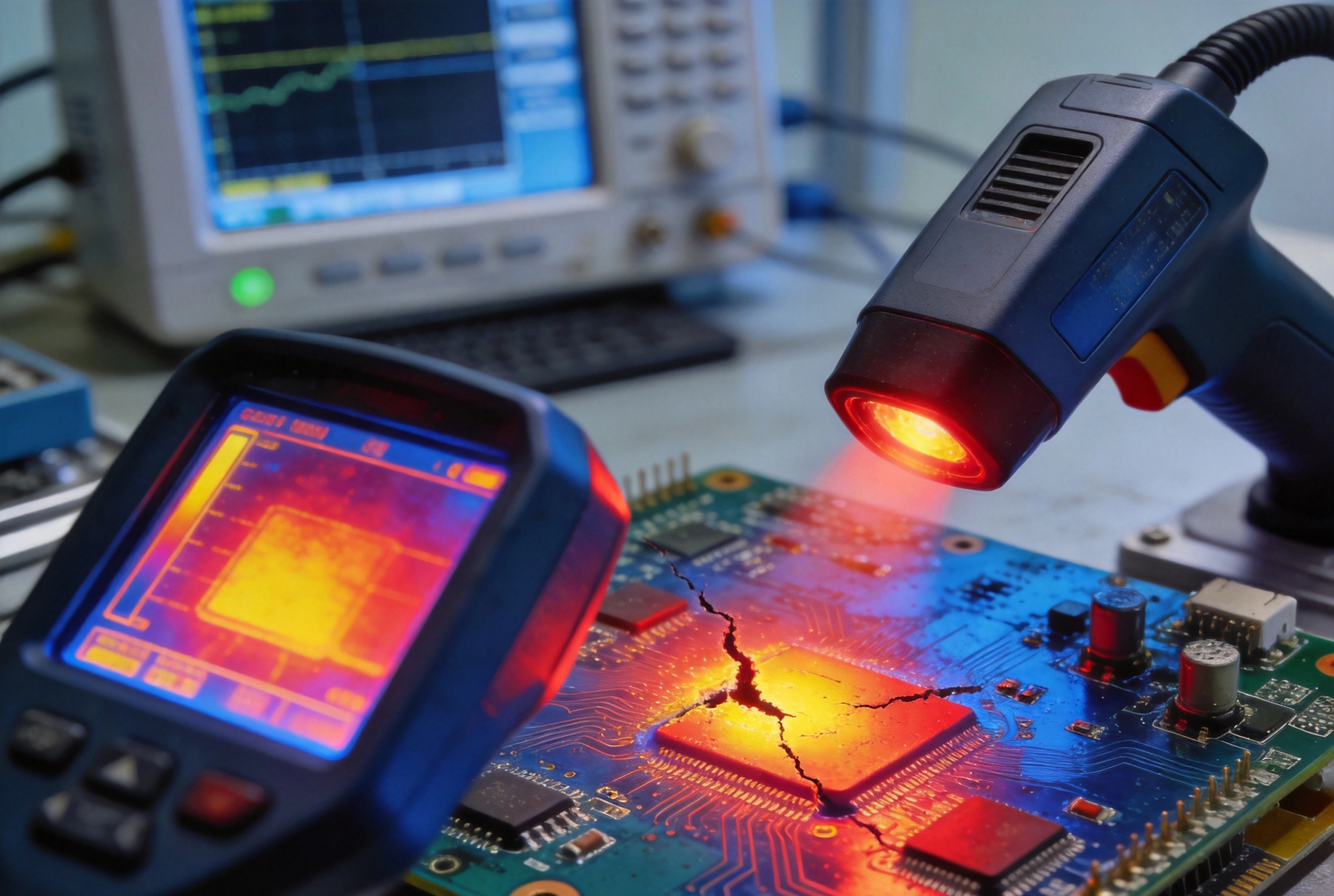
Industrial environments subject circuit boards to stresses far beyond typical consumer applications. Temperature extremes, humidity fluctuations, vibration, chemical exposure, and electrical transients combine to create failure mechanisms rarely encountered in controlled office or home environments. A single failure mechanism may trigger cascading failures as damaged circuits affect adjacent components or Thermal Management degrades.
Root cause analysis of failed boards reveals consistent patterns across industries and applications. While every assembly has unique characteristics, failure mode distribution follows predictable patterns that enable targeted reliability improvement. Field failure data from multiple sources confirms that the same five categories account for the majority of Industrial Pcb failures worldwide.
The financial impact of Industrial Pcb failure dramatically exceeds the board cost itself. A failed PLC controller in an automotive assembly line can cost thousands of dollars per hour in lost production. Medical equipment failures may require immediate backup systems or create patient safety concerns. Infrastructure controls for water treatment or power distribution cannot tolerate extended downtime. These application-critical deployments demand reliability levels that exceed consumer electronics by orders of magnitude.
Beyond direct repair costs, field failures create warranty liabilities, customer dissatisfaction, and reputation damage that affect future business. Products with poor reliability histories face reduced market acceptance regardless of their functional capabilities. The competitive disadvantage of poor reliability often exceeds direct failure costs by an order of magnitude over the product lifecycle.
Thermal fatigue represents the leading cause of industrial PCB failure in most reliability studies. Components and solder joints expand and contract with temperature changes, and the different thermal expansion coefficients of dissimilar materials create cyclic stress at interfaces. Over thousands or millions of thermal cycles, these stresses gradually crack solder joints, delaminate interfaces, and fracture component terminations.
Industrial equipment experiences Thermal Cycling from multiple sources. Process equipment may cycle between ambient and elevated temperatures as operational demands vary. Equipment in unheated buildings faces seasonal temperature swings. Power dissipation from components creates self-heating that adds to environmental temperature swings. The combination of multiple cycling sources accelerates fatigue damage accumulation.
Thermal Management design significantly affects cycling fatigue life. Components should be arranged to minimize thermal coupling that creates temperature gradients across critical joints. Thermal relief patterns in ground planes reduce heat spreading to sensitive components while maintaining adequate cooling for power devices. Strategic component placement reduces the temperature differential between adjacent parts, lowering cyclic stress magnitudes.
Material Selection influences thermal fatigue resistance. Lead-free solder alloys exhibit higher Young's modulus than traditional tin-lead solder, creating greater stress for equivalent strain. High-tg Pcb substrates reduce mismatch between component and board thermal expansion coefficients. Ceramic-filled substrates provide intermediate thermal expansion that better matches component coefficients compared to standard glass-reinforced materials.
Manufacturing processes affect how well assemblies resist thermal fatigue. Void-free solder joints resist crack initiation at the component interface. Proper reflow profiles ensure complete wetting without excessive intermetallic compound formation that creates brittle joints. Underfill materials for ceramic components reduce stress concentration at the die-attach interface.
Mechanical support features built into the Pcb Design help absorb thermal stress. Strain Relief clips, reinforced mounting areas, and flexible cable attachments reduce stress transmitted to solder joints during thermal excursions. Encapsulation compounds absorb thermal expansion mismatch when properly selected for the operating temperature range.
Industrial machinery generates continuous vibration that fatigues solder joints and loosens connections over time. Motors, pumps, conveyors, and HVAC equipment all produce vibration frequencies that couple into nearby electronic controls. Equipment installed on vehicles or mobile platforms faces even more severe vibration from engine operation and road surfaces. Vibration-induced failures account for a substantial fraction of field returns in industrial applications.
Vibration damages PCBs through multiple mechanisms. High-frequency vibration causes cyclic stress in solder joints, eventually cracking interconnects. Large components like electrolytic capacitors have mass that amplifies vibration acceleration, accelerating fatigue at their terminations. Connectors and cable attachments experience cyclic loading that can work loose if not properly secured.
Pcb Layout significantly affects vibration survivability. Heavy components should be positioned near mounting points where board deflection is minimal. Component placement should avoid areas of maximum board flex, typically the center span between mounting points. Stiffening ribs or metal backing plates increase board natural frequencies above excitation frequencies.
Component selection matters for vibration-sensitive applications. Tantalum capacitors are particularly susceptible to vibration-induced failure due to their construction. Surface mount components generally outperform through-hole parts for vibration resistance because their solder fillet provides more robust mechanical attachment to the board surface. When through-hole parts are required, the solder fillet inside the barrel provides additional strength compared to surface mount alone.
Physical mounting arrangements determine how vibration energy couples into circuit boards. Shock mounts isolate equipment from platform vibration when the application permits. Rigid mounting to substantial structural members reduces relative motion transmitted to the PCB. Isolation mounts work by allowing the equipment to move independently of the vibrating platform, reducing relative motion at the circuit board.
Secondary retention prevents catastrophic failure when primary mounting fails. Lock washers, thread-locking compounds, and adhesive bonding supplement solder joints for through-hole components. Cable ties and strain reliefs prevent disconnected wires from creating open circuits. Potting and encapsulation protect against vibration and provide additional mechanical support for vulnerable components.
Moisture causes PCB failures through multiple mechanisms that degrade insulation resistance, promote corrosion, and create electrical shorts. Ionic contamination from manufacturing residues combines with absorbed moisture to form conductive pathways that cause leakage current, electrochemically migrate metal between traces, and create dendritic growths that short adjacent conductors. Industrial environments with humidity, washdown procedures, or chemical exposure intensify these failure mechanisms.
Hygroscopic materials in PCB construction absorb moisture that expands during reflow soldering, causing Delamination and cracking. Popcorning occurs when moisture vapor pressure during solder heating forces apart component packages and substrates. This failure mode particularly affects components packaged in moisture-sensitive trays or tubes that may have absorbed humidity during storage or transit.
Conformal Coating provides a protective barrier against moisture and contamination for sensitive circuit areas. Acrylic coatings offer good general protection with easy reworkability. Urethane coatings provide superior chemical and moisture resistance for demanding environments. Parylene coatings provide excellent barrier properties with minimal thickness, but processing complexity limits their use to high-value assemblies.
Full encapsulation using potting compounds provides the most complete protection against moisture ingress. These materials completely surround the PCB, eliminating pathways for moisture to reach conductors and components. Thermal Conductivity considerations must balance protection with adequate Heat Dissipation. Some potting compounds degrade at high temperatures, limiting their use near power components.
Residual flux and other manufacturing contamination accelerate moisture-related failures. Ionic residues create conductive pathways under moisture exposure, causing leakage current that degrades circuit performance or creates safety hazards. Cleaning standards for industrial and medical applications require lower contamination levels than consumer electronics.
No-clean processes reduce contamination risk by eliminating the need for post-assembly cleaning. These processes use solder pastes and fluxes designed to leave benign residues that do not require removal. However, no-clean residues may still cause problems in high-voltage or high-impedance circuits, requiring selective cleaning of critical areas even when using no-clean materials.
Conductive Anodic Filament formation (CAF) represents one of the most insidious PCB failure mechanisms, particularly in multilayer boards. CAF occurs when moisture and voltage gradients drive copper ion migration through the Pcb Substrate between adjacent traces. This migration creates conductive filaments that eventually bridge traces, creating shorts that can damage circuits or create safety hazards.
CAF failure typically occurs after extended field service, often after months or years of reliable operation. The gradual growth of conductive filaments means that assemblies pass all tests at delivery but fail in service as the migration process reaches the bridging threshold. This delayed failure pattern makes root cause analysis challenging and increases warranty cost exposure.
Pcb Substrate materials vary significantly in CAF resistance. Standard FR-4 with woven glass reinforcement provides pathways through the weave pattern where resin and glass intersect. High-performance materials with tighter Quality Control and alternative reinforcement constructions reduce CAF pathways. Panasonic Megtron, Isola I-Tera, and Rogers materials offer improved CAF resistance compared to standard FR-4.
Trace spacing and voltage gradient influence CAF growth rate. Higher voltages create stronger driving force for ion migration. Tighter spacing between traces reduces the distance that conductive filaments must grow to cause bridging. Design rules for high-reliability applications specify minimum spacings based on voltage and environmental conditions.
Conformal Coating or encapsulation eliminates moisture access that enables CAF growth. When properly applied and maintained, these coatings prevent the electrolyte necessary for ion migration. However, coating defects or damage can create localized moisture accumulation that actually concentrates the electrolyte and accelerates local CAF growth.
Voltage and spacing design rules provide margin against CAF failure in uncoated assemblies. Ipc Standards provide guidance on spacing requirements based on voltage levels and environmental exposure. Designs exceeding these spacing guidelines provide additional margin against the variability inherent in manufacturing processes and field conditions.
Electrical overstress from transients, electrostatic discharge, and overvoltage conditions damages components and traces that may fail immediately or degrade gradually over time. Industrial environments contain numerous sources of electrical transients including motor starting, relay switching, lightning discharge, and power system faults. These events inject energy into electronic circuits at levels far exceeding normal operating conditions.
ESD damage ranges from obvious catastrophic failures to subtle latent defects that manifest only under specific conditions. Components that survive initial ESD exposure may have accumulated damage that reduces reliability or causes intermittent operation. Detecting ESD damage after the fact is challenging because damage may not affect functionality until triggered by subsequent stress.
TVS diodes and transient suppression components clamp voltage transients before they reach sensitive circuits. Selection of appropriate clamping voltage and peak current rating determines protection effectiveness. Placement as close as possible to the protected node minimizes inductance that delays clamping response. Multiple protection stages address different transient types and magnitudes.
Series resistance and current limiting protect high-impedance circuits from overcurrent damage. Fuses and polyfuses provide overcurrent protection that isolates faults before damage propagates. Careful selection of trip characteristics balances protection responsiveness against nuisance tripping during normal transients.
Signal routing affects circuit susceptibility to electrical disturbances. Long loops act as antennas that pick up radiated interference. Shielded cables and twisted pair routing reduce susceptibility to electromagnetic coupling. Ground plane integrity provides return path management that minimizes loop area and improves immunity.
Component placement affects both susceptibility and protection effectiveness. Sensitive circuits should be separated from high-current switching circuits that generate transients. Protection components should be placed at entry points where transients enter the PCB from external connections. Filtering components remove high-frequency noise before it reaches sensitive circuitry.
Individual Pcb Reliability improvement contributes to system-level reliability, but overall equipment reliability depends on how PCBs interact within the complete system. Redundancy, graceful degradation, and built-in-test all influence how equipment performs when individual components fail. These system-level approaches provide additional protection beyond PCB-level improvements.
Predictive maintenance using condition monitoring detects impending failures before they cause unexpected downtime. Temperature monitoring, vibration sensing, and electrical parameter trending can identify degradation before catastrophic failure occurs. These approaches require instrumentation during design but enable maintenance optimization that extends equipment life while preventing failures.
Manufacturing quality directly affects field reliability regardless of design excellence. Incoming inspection and supplier qualification ensure that purchased components and assemblies meet reliability requirements. Statistical process control monitors manufacturing consistency and identifies drift before out-of-specification conditions cause field failures.
Supplier audits verify that manufacturing processes maintain the quality systems necessary for reliable production. ISO 9001 certification provides baseline quality system requirements, while industry-specific standards like Iatf 16949 for automotive or AS9100 for aerospace address sector-specific reliability requirements. Regular audits maintain supplier awareness that quality performance is monitored and affects purchasing decisions.
Burn-in testing accelerates early-life failures by operating assemblies under stress conditions that activate latent defects. Temperature cycling, electrical stress, and extended operation at elevated temperature identify weak assemblies before they reach customers. Burn-in requirements for industrial applications typically exceed consumer electronics requirements due to the higher reliability expectations.
Functional test coverage affects defect detection sensitivity. Comprehensive Functional Testing with stress conditions catches more defects than basic go/no-go testing. Design For Testability features including Test Points, scan chains, and Boundary Scan improve fault detection coverage. Higher test coverage reduces field defect rates by catching problems before shipment.
Systematic reliability improvement requires understanding current failure modes, prioritizing improvement opportunities, and tracking progress over time. Field failure data analysis identifies the most impactful failure categories. Pareto analysis focuses improvement efforts on the failure modes causing the majority of field returns. Root cause analysis ensures that improvement actions address underlying causes rather than symptoms.
Design for reliability processes incorporate lessons learned from previous products and field experience. Reliability Prediction tools estimate field failure rates based on component counts, stress levels, and environmental conditions. Failure mode and effects analysis (FMEA) identifies potential failure modes and their consequences early in design when changes cost least.
Sustained reliability improvement requires organizational commitment beyond individual projects. Reliability metrics tracked over time reveal trends that individual project data might miss. Cross-functional teams combining design, manufacturing, and quality engineering perspectives identify improvement opportunities that single-function approaches might miss.
Supplier partnerships enable collaborative reliability improvement that benefits both parties. Sharing field failure data with key suppliers helps them understand failure patterns and prioritize their own improvement efforts. Joint problem-solving accelerates root cause identification and corrective action implementation. Long-term relationships create incentives for suppliers to invest in reliability improvements.
Industrial Pcb Reliability depends on addressing the five primary failure mechanisms: thermal fatigue, vibration damage, moisture ingress, Electrochemical Migration, and electrical overstress. Each failure category requires specific design approaches, material selections, and manufacturing controls that together create robust assemblies capable of extended reliable service.
Improving reliability requires systematic analysis of actual field failures to prioritize improvement efforts. Design guidelines, material specifications, and process controls all contribute to reliability achievement. Testing and screening catch defects before field deployment, while supplier quality management ensures consistent manufacturing quality.
The investment in reliability improvement pays returns through reduced warranty costs, improved customer satisfaction, and enhanced competitive positioning. Products that work reliably in demanding industrial environments build reputations that support premium pricing and repeat business. For engineers and managers responsible for Industrial Electronics, mastering these reliability fundamentals creates products that customers can depend on when failure is not an option.
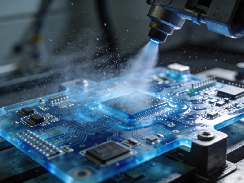
The Role of Conformal Coating in Enhancing Industrial PCB ReliabilityJuly/17/2026
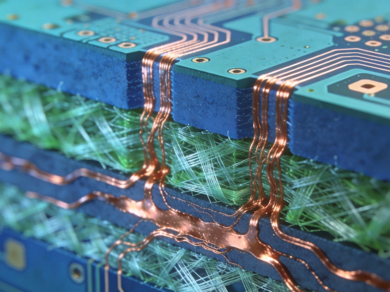
How to Prevent Electrochemical Migration (CAF) for Better Industrial PCB ReliabilitySeptember/04/2026
How to Enhance the Mechanical Strength of HDI StructuresSeptember/07/2026
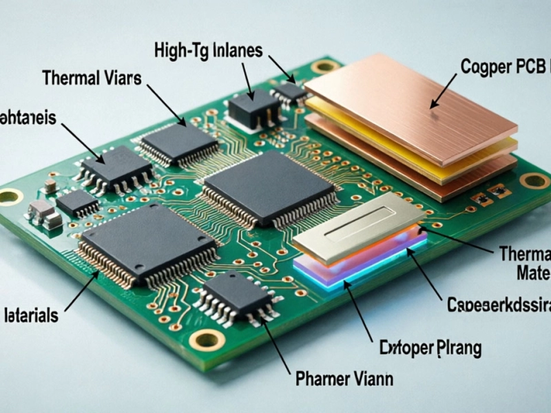
Thermal Management Strategies for Long-Term Industrial PCB ReliabilityJune/04/2026
Ensuring Industrial PCB Reliability in Extreme Environmental ConditionsMay/27/2026
Vibration and Shock: Designing for Industrial PCB Reliability in AutomationJune/30/2026
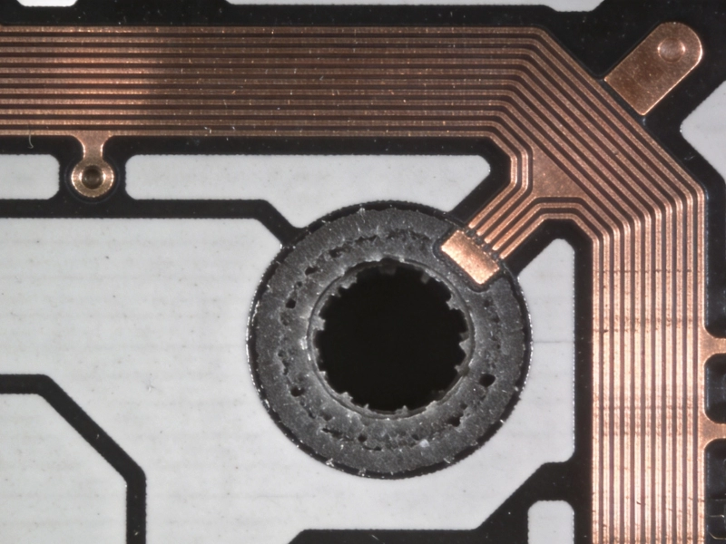
Identifying and Fixing Micro-Vias Issues in Industrial PCB Quality InspectionsSeptember/10/2026
A Comprehensive Guide to High-Tg Materials for Industrial PCBsMay/27/2026