Your industrial control system failed after 18 months of reliable operation. The field return shows a short circuit between two adjacent vias—yet the board passed every test at manufacture. What happened? The culprit is likely Conductive Anodic Filament (CAF), one of the most insidious failure mechanisms in multilayer PCBs. Unlike immediate failures that reveal themselves in testing, CAF failures emerge silently over months or years, often after the warranty period expires.
Understanding CAF formation, knowing the risk factors, and implementing prevention strategies can mean the difference between products that last decades and those that fail prematurely. This guide covers everything Industrial Pcb designers and manufacturers need to know about Caf Prevention.

What is Electrochemical Migration (CAF)?
Electrochemical migration is the process by which metal ions migrate through an electrically insulating material under the influence of an electric field. When this occurs within a Pcb Substrate—specifically between adjacent conductive features like vias or traces—it creates conductive pathways called dendrites or filaments.
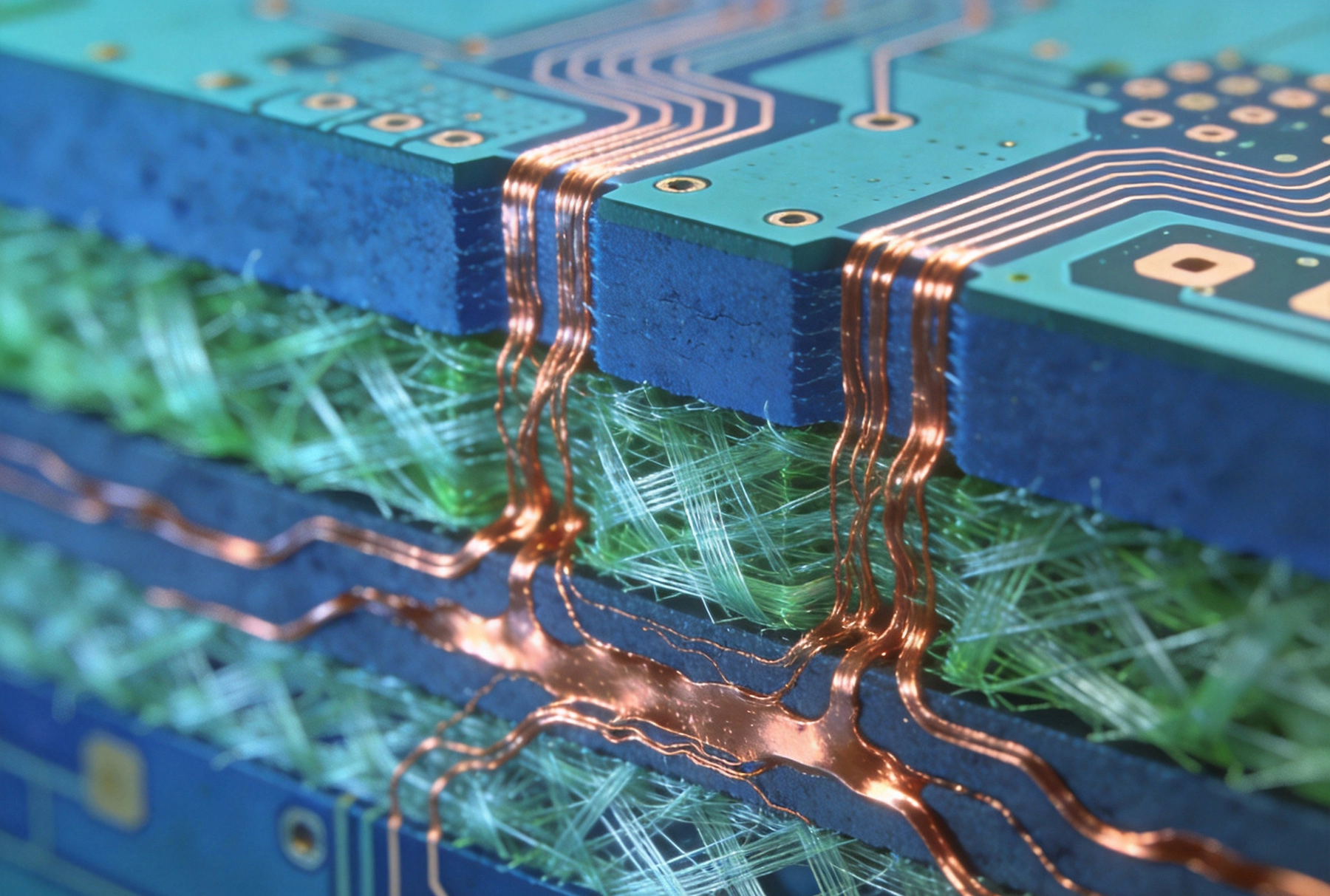
The term CAF specifically refers to Conductive Anodic Filament formation. Here's the mechanism:
-
Activation: Moisture and ionic contamination penetrate the Pcb Substrate at high humidity or when exposed to water.
-
Ionization: At the anode (positive voltage), copper atoms lose electrons and become copper ions (Cu²⁺).
-
Migration: These ions travel through the PCB dielectric toward the cathode (negative voltage).
-
Deposition: At the cathode, ions regain electrons and deposit as metallic copper, forming conductive filaments.
-
Failure: The growing filament eventually bridges the gap between conductors, causing a short circuit.
CAF typically grows along the glass fiber bundles in the PCB substrate—the interface between resin and glass provides a pathway of lower resistance than solid resin. This is why CAF is particularly associated with fiberglass-reinforced substrates like FR-4.
Why CAF Matters for Industrial Applications
Industrial environments create conditions that accelerate CAF formation. Understanding why industrial PCBs are particularly vulnerable helps justify the investment in Caf Prevention.
Harsh Operating Environments
-
High humidity: Factory floors, outdoor installations, and climate-controlled equipment experience humidity cycling that drives moisture into PCB substrates.
-
Temperature cycling: Thermal expansion and contraction creates stress at the resin-glass interface, potentially creating microcracks that provide pathways for CAF.
-
Vibration and mechanical stress: Industrial machinery produces vibration that can degrade PCB integrity over time.
-
Chemical exposure: Industrial chemicals, cleaning agents, and atmospheric pollutants can accelerate degradation.
Reliability Requirements
Industrial equipment often has lifetime requirements of 10-20 years. The longer a product operates, the more opportunity for CAF to form and cause failure. Field failures damage reputation, increase warranty costs, and may create liability exposure.
Remote and Inaccessible Installations
Industrial control systems are often installed in locations that are difficult to access. A field service call to replace a failed board costs far more than implementing CAF-resistant design from the start. Prevention is always cheaper than field failure.
The CAF Failure Mechanism in Detail
Understanding exactly how CAF forms helps you identify the best prevention strategies. Let's examine the electrochemical and materials science behind the mechanism.
The Role of Glass Fiber Bundles
Standard Fr-4 Laminate consists of woven glass fiber reinforcement bonded with epoxy resin. The weaving process creates two distinct regions:
-
Glass fiber bundles: Areas where multiple glass filaments are grouped together
-
Resin-rich regions: Areas between bundles, filled primarily with epoxy
The glass-resin interface is never perfectly bonded. Voids, microcracks, and incomplete resin fill create pathways between the glass and resin. When moisture penetrates the substrate, it follows these pathways—and electrical fields cause ions to migrate along them.
Voltage Gradient Effects
CAF growth is directional—it follows the voltage gradient between conductors. Higher voltage differences accelerate ion migration. In practical terms:
-
Higher voltage nets are at greater risk
-
The rate of growth increases with applied voltage
-
Growth typically occurs perpendicular to voltage gradient lines
Humidity and Moisture
Moisture is the essential catalyst. Without moisture, ion migration cannot occur. The sources of moisture include:
-
Ambient humidity: Boards operating in humid environments absorb moisture over time
-
Condensation: Temperature cycling through the dew point causes moisture to condense on board surfaces
-
Process water: Residue from aqueous manufacturing processes if not properly dried
-
Delivered moisture: Some applications explicitly expose boards to water
Key Risk Factors for CAF
Several factors determine whether CAF will occur in a given PCB. Design and manufacturing decisions can minimize these risks.
Material Selection
Laminate Types and CAF Resistance
Not all laminates are equally resistant to CAF. Material choices significantly impact reliability:
-
Standard FR-4: Moderate CAF resistance; suitable for benign environments but risky in harsh conditions
-
High-tg Fr-4: Improved thermal performance; Tg of 170°C+ reduces risk of thermal degradation
-
Polyimide: Excellent CAF resistance due to better glass-resin bonding and higher thermal capability
-
BT (Bismaleimide-Triazine): Good CAF resistance; common in high-reliability applications
-
Low-flow prepregs: Less resin flow during lamination means better glass-resin interface integrity
Resin Content and Distribution
The amount and distribution of resin in the laminate affects CAF susceptibility:
-
Resin content: Higher resin content generally improves CAF resistance by filling glass fiber gaps
-
Resin flow: Controlled flow during lamination affects void formation at the interface
-
Resin richness: Resin-rich formulations provide better protection
Design Factors
Via Spacing and Configuration
The spacing between vias is one of the most critical design factors. Closer spacing means shorter pathways for CAF growth:
-
Ipc Class 3 recommendations: Minimum spacing varies by voltage; higher voltages require greater spacing
-
Voltage differential: Larger voltage differences accelerate CAF growth
-
Via-to-via distance: CAF typically bridges distances of 0.5-2mm, but growth can continue beyond initial formation
Elevated temperatures accelerate the electrochemical processes that drive CAF:
-
Local heating from components increases temperature at risk areas
-
Thermal gradients create stress that can delaminate the glass-resin interface
-
Repeated Thermal Cycling compounds these effects over time
Manufacturing Influences
Lamination Quality
The lamination process directly affects glass-resin interface quality:
-
Temperature and pressure profiles: Must be optimized for the specific laminate system
-
Resin flow control: Too little flow leaves voids; too much flow depletes resin content
-
Vacuum assistance: Reduces trapped air and voids during lamination
Drilling Quality
Via formation affects CAF susceptibility:
-
Resin smear: Incomplete desmear leaves residual resin that can trap moisture
-
Heat generation: Excessive drilling heat can damage the glass-resin interface
-
Hole wall quality: Rough or contaminated hole walls provide pathways for ion migration
Plating Quality
Copper plating in vias must be defect-free:
-
Void-free plating: Voids in plating trap moisture and create pathways
-
Adhesive coverage: Copper must bond well to the substrate to prevent Delamination
-
Uniformity: Even plating thickness prevents weak points
Design Guidelines for CAF Prevention
Applying CAF-resistant design principles early in the design process prevents costly redesigns later.
Spacing and Clearance Rules
Increase spacing between high-voltage nets and any adjacent grounded features. Specific guidelines:
-
For voltages above 50V, maintain minimum spacing per Ipc Class 3 guidelines
-
For critical high-reliability applications, consider doubling the minimum spacing
-
Route high-voltage signals away from vias in ground planes where possible
-
Avoid placing vias in direct line with voltage gradients
Via Protection Strategies
Stacked vs. Staggered Vias
The via configuration affects CAF risk:
-
Stacked vias: Direct vertical alignment; if one fails, the failure propagates directly
-
Staggered vias: Offset arrangement; requires CAF to grow horizontally as well as vertically, slowing growth
-
Blind/buried vias: Reduced interface area means fewer potential pathways
Via-in-pad designs require special attention:
-
Via fill materials must provide moisture barrier
-
Plugging and capping techniques affect resistance
-
Electroplated fill provides better protection than conductive paste
Trace and Plane Design
-
Use ground planes: Ground planes adjacent to signal layers reduce field strength
-
Guard traces: Shield sensitive traces from high-voltage nets
-
Creepage distance: Account for surface distance, not just straight-line spacing
Material Selection Strategies
Choosing the right materials for your application environment is one of the most effective CAF prevention strategies.
Choosing the Right Laminate
Application Environment Assessment
Evaluate your operating environment honestly:
-
85/85 testing conditions: Boards may see 85°C and 85% humidity
-
Temperature range: Wider ranges cause more thermal stress
-
Chemical exposure: Presence of solvents, fuels, or cleaning agents
-
Expected lifetime: Longer lifetimes require higher reliability margins
Material Alternatives to Standard FR-4
For demanding applications, consider these alternatives:
-
High-reliability FR-4: Specially formulated with better resin-glass bonding
-
Halogen-free laminates: Some halogen-free formulations show improved CAF resistance
-
Polyimide: Excellent thermal and CAF performance; higher cost
-
MEGTRON: Panasonic material with excellent CAF resistance for telecom/infrastructure
-
Nelco N4000: High-performance laminate with good CAF resistance
Prepreg Selection
Prepreg (pre-impregnated resin) choices affect laminate quality:
-
Resin content: Higher resin content generally improves CAF resistance
-
Flow characteristics: Medium-flow prepregs often provide best balance
-
Thickness: Adequate thickness ensures complete resin coverage
Manufacturing Process Control
Even the best design can fail if manufacturing doesn't meet quality standards. Manufacturing process control is essential for CAF prevention.
Lamination Best Practices
-
Validate lamination parameters for each laminate type
-
Use vacuum lamination when available
-
Control cooling rates to minimize thermal stress
-
Verify void-free construction with microsection analysis
Drilling and Desmear
-
Optimize drill parameters (rpm, feed rate) to minimize heat damage
-
Perform adequate desmear to remove resin smear without damaging substrate
-
Control electroless copper coverage to ensure good adhesion
Plating and Processing
-
Maintain plating bath chemistry within specifications
-
Verify hole wall coverage with microsections
-
Minimize time between processes to prevent moisture absorption
-
Ensure adequate drying before storage or shipment
Testing and Validation
Verifying CAF resistance through testing helps validate your design and material choices.
Accelerated Life Testing
85/85 Testing
The industry-standard test for CAF susceptibility:
-
Conditions: 85°C temperature, 85% relative humidity, biased voltage
-
Duration: Typically 500-1000 hours minimum
-
Bias: Apply voltage to accelerate ion migration
-
Monitoring: Track insulation resistance over time
Failure is typically defined as insulation resistance dropping below a threshold (e.g., 100MΩ) or a short circuit occurring.
Temperature-Humidity-Bias (THB) Testing
Similar to 85/85 but may use different conditions:
-
65°C/90%RH is common for consumer applications
-
Higher temperatures accelerate failure mechanisms
-
Combined with voltage bias for worst-case conditions
Design for Test (DFT) Considerations
-
Include test coupons that replicate production board construction
-
Design test structures to evaluate specific risk areas
-
Use interdigitated patterns to accelerate failure detection
CAF vs. Other Failure Mechanisms
CAF is one of several electrochemical failure mechanisms. Understanding the differences helps with diagnosis and prevention.
CAF vs. Dendrite Growth
Both involve metal migration, but in different locations:
-
Dendrite growth: Occurs on PCB surfaces; visible as tree-like structures between traces
-
CAF: Occurs within the PCB substrate; not visible without destructive analysis
-
Prevention differs: Surface dendrites need Conformal Coating; CAF requires material and design changes
CAF vs. Conductor Corrosion
Both involve electrochemical reactions:
-
Conductor corrosion: Metal oxidizes in place, increasing resistance or breaking circuits
-
CAF: Metal migrates from anode to cathode, creating conductive bridges
-
Both require moisture: But CAF requires voltage bias; corrosion can occur without bias
CAF vs. Delamination
Delamination and CAF can be related:
-
Delamination: Separation at the glass-resin interface; may be visible
-
CAF: Growth along the same interface; not visible
-
Relationship: Delamination creates pathways that can accelerate CAF
Industry Standards and Guidelines
Several industry standards address CAF and related reliability concerns.
IPC Standards
-
IPC-4101: Specification for base materials for rigid and multilayer printed boards (includes CAF requirements)
-
Ipc-6012: Qualification and performance specification for rigid printed boards
-
IPC-TM-650: Test methods manual, including methods for CAF testing
Application-Specific Standards
-
Automotive: AEC-Q200 for passive components; OEM-specific requirements
-
Aerospace: MIL-PRF-31032 and MIL-PRF-55110 for military PCBs
-
Telecom: Bellcore/Telcordia standards for telecommunications equipment
Cost Considerations
CAF prevention has costs. Balancing these against reliability requirements and failure costs helps make good business decisions.
Design and Material Costs
-
Premium materials: May cost 20-100% more than standard FR-4
-
Increased spacing: May require larger board or more layers
-
Additional testing: 85/85 testing adds time and cost to qualification
Failure Costs
-
Field service calls: Often $1000-5000 per failure in industrial applications
-
Product returns: Direct costs plus shipping and handling
-
Reputation damage: Hard to quantify but real impact on future sales
-
Warranty reserves: Financial liability for predicted failure rates
-
Liability exposure: In extreme cases, product failures create legal liability
Risk-Based Decision Making
The right investment in CAF prevention depends on your specific situation:
-
High-reliability applications: Invest heavily in prevention; failure is unacceptable
-
Consumer products: May accept higher risk given lower warranty costs
-
Industrial equipment: Moderate investment justified by field service costs
Summary: CAF Prevention Checklist
Here's a consolidated checklist for CAF-resistant Pcb Design and manufacturing:
Design Phase
-
Select materials appropriate for your application environment
-
Increase spacing between high-voltage nets beyond minimum requirements
-
Use staggered vias rather than stacked vias where possible
-
Route high-voltage signals away from via密集 areas
-
Include ground planes adjacent to high-risk signal layers
-
Consider polyimide or other high-reliability materials for harsh environments
Manufacturing Phase
-
Validate lamination parameters with your fabricator
-
Verify drilling parameters minimize heat damage
-
Confirm adequate desmear for void-free plating
-
Use microsection analysis to verify construction quality
-
Control moisture exposure during storage and handling
Qualification Phase
-
Conduct 85/85 biased testing for critical products
-
Include test coupons that replicate production construction
-
Monitor insulation resistance during Accelerated Life Testing
-
Document test results and failure modes
Conclusion
Conductive Anodic Filament formation is a serious threat to Industrial Pcb reliability, but it's a threat that can be managed through proper design, Material Selection, and manufacturing control. The mechanisms of CAF are well understood, and effective prevention strategies exist.
The key is applying CAF awareness early in the design process, when changes are inexpensive, rather than discovering CAF susceptibility after production begins. Invest in Material Selection, spacing decisions, and design practices that minimize risk. Work with manufacturing partners who understand CAF and maintain appropriate process controls.
The cost of prevention is small compared to the cost of field failures. For industrial applications where reliability is paramount and field service is expensive, CAF prevention isn't optional—it's essential engineering practice.
Frequently Asked Questions
What is the typical time to CAF failure?
CAF failures typically occur after 500-2000 hours of operation under stressed conditions (85°C/85%RH with voltage bias). In benign environments, CAF may never develop. The growth rate depends on voltage, humidity, temperature, and material properties. Under worst-case conditions, failures can occur within weeks; under normal operating conditions, failure may take years.
Can conformal coating prevent CAF?
Conformal Coating provides a barrier against moisture and can slow CAF initiation, but it cannot prevent CAF entirely. CAF forms within the substrate, where coating cannot reach. Once moisture penetrates the substrate (which happens over time even with coating), conditions for CAF exist. Material selection and design remain the primary prevention strategies.
What spacing is required to prevent CAF?
IPC guidelines provide minimum spacing recommendations based on voltage, but these are general guidelines, not CAF-specific. For high-reliability applications, many designers double the minimum spacing. The appropriate spacing depends on voltage, laminate material, operating environment, and expected lifetime. Work with your fabricator to determine appropriate spacing for your specific application.
How do you detect CAF failures?
CAF failures are difficult to detect because the filaments form inside the substrate. Common detection methods include: insulation resistance monitoring (reveals degradation before short circuit), Failure Analysis cross-sectioning (destructive method revealing internal filaments), and X-ray Inspection (can reveal some CAF formations in certain configurations).
Is CAF only a problem in multilayer boards?
CAF is most commonly associated with multilayer boards because the internal construction creates glass-resin interfaces. However, similar electrochemical migration can occur in other constructions. Single-sided and double-sided boards with plated through-holes can experience similar issues, though the risk is generally lower due to simpler construction.
Need help designing PCBs for maximum CAF resistance? Our engineering team can review your design and recommend appropriate materials and design practices.