Open Nav


Selecting the right dielectric material for a high-frequency PCB is one of the most consequential decisions an RF engineer makes. The material's Dielectric Constant (Dk) and dissipation factor (Df) directly determine insertion loss, impedance control accuracy, and signal propagation velocity—parameters that ultimately define whether a design meets its link buget or falls short. In the high-frequency Pcb Materials landscape, two families dominate the conversation: Rogers Corporation's ceramic-filled hydrocarbon laminates (the RO4000 series, RO3000 series, and their derivatives) and PTFE-based laminates (pure PTFE, glass-reinforced PTFE, and ceramic-filled PTFE from manufacturers like Taconic, Arlon, and Rogers' own RT/Duroid line). While both categories serve high-frequency applications, they differ significantly in electrical properties, mechanical behavior, manufacturability, and cost. This article provides a detailed, application-focused comparison to help engineers choose the right material system for their specific high-frequency design.
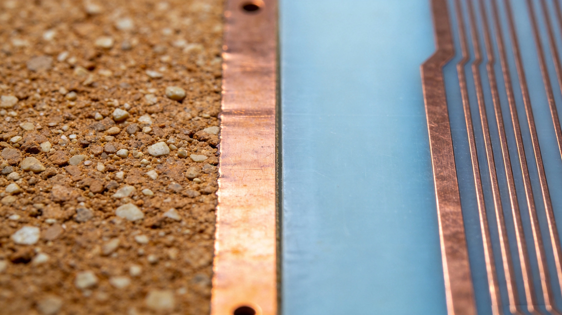
The Rogers RO4000 series (RO4003C, RO4350B, RO4835, RO4360) uses a proprietary ceramic-filled hydrocarbon thermoset resin system. Unlike PTFE, these materials are not fluoropolymer-based—they are thermoset plastics loaded with ceramic fillers that achieve low Dk and low Df without the processing difficulties of PTFE. Key characteristics:
PTFE (Polytetrafluoroethylene)—the polymer behind Teflon—has exceptional dielectric properties: Dk of 2.1 and Df of 0.0004 at 10 GHz for pure PTFE. These properties make it the gold standard for low-loss RF applications, but pure PTFE is mechanically soft and thermally challenging to process. PTFE PCB laminates come in several variants:
The primary reason engineers select high-frequency materials is electrical performance. Here is how Rogers hydrocarbon and PTFE laminates compare across the key electrical parameters.
| Material | Dk (10 GHz) | Dk Tolerance |
|---|---|---|
| Rogers RO4003C | 3.38 | ±0.05 |
| Rogers RO4350B | 3.48 | ±0.05 |
| Rogers RO4360 | 6.15 | ±0.15 |
| PTFE (RT/Duroid 5880) | 2.20 | ±0.02 |
| Glass-PTFE (RF-35) | 3.50 | ±0.05 |
| Ceramic-PTFE (CER-10) | 10.0 | ±0.25 |
| Standard FR4 | 4.50 | ±0.10 |
Key observations:
| Material | Df (10 GHz) | Insertion Loss* (dB/in, 10 GHz) |
|---|---|---|
| Rogers RO4003C | 0.0027 | 0.50 |
| Rogers RO4350B | 0.0037 | 0.65 |
| PTFE (RT/Duroid 5880) | 0.0004 | 0.15 |
| Glass-PTFE (RF-35) | 0.0018 | 0.40 |
| Standard FR4 | 0.020 | 2.10 |
*50Ω Microstrip, 1 oz copper, representative values; actual loss depends on copper roughness and trace geometry.
The Df comparison reveals the clearest advantage of PTFE: pure PTFE has roughly 7× lower Df than Rogers RO4003C, and this advantage grows at higher frequencies where Df differences have a proportionally greater impact on insertion loss. For a 10-inch RF trace at 28 GHz (mmWave 5G), the insertion loss difference between RO4003C (approximately 1.5 dB) and RT/Duroid 5880 (approximately 0.4 dB) is over 1 dB—a margin that can determine whether a link budget closes or not.
However, glass-reinforced PTFE materials (the type most commonly used in practical PCB construction) have Df values much closer to Rogers hydrocarbon materials. The glass fiber itself contributes loss, and the PTFE-glass interface creates additional dielectric loss mechanisms. For glass-PTFE at Dk 3.5, the Df is typically 0.0015–0.0020—only modestly better than Rogers RO4350B at 0.0037.
Both Rogers hydrocarbon and PTFE materials address the glass weave effect that plagues standard FR4, but in different ways:
Electrical performance is necessary but not sufficient—a PCB material must also survive the manufacturing process and the operating environment. Here the comparison shifts strongly in favor of Rogers.
| Material | CTE X-Y (ppm/°C) | CTE Z (ppm/°C) |
|---|---|---|
| Rogers RO4003C | 11–14 | 30–40 |
| Rogers RO4350B | 11–14 | 30–40 |
| PTFE (RT/Duroid 5880) | 31 (X), 48 (Y) | 237 |
| Glass-PTFE (RF-35) | 13–17 | 50–70 |
| Standard FR4 | 14–17 | 50–70 |
The CTE data reveals a critical weakness of unreinforced PTFE: a Z-axis CTE of 237 ppm/°C—roughly 6× higher than FR4 and 8× higher than Rogers hydrocarbon. This enormous Z-axis expansion means that plated through-holes in pure PTFE boards are subjected to extreme thermal stress during soldering and operational temperature cycling. Via cracking and barrel fracture are common failure modes for PTFE boards with many through-hole vias, limiting the reliability of pure PTFE constructions in thermally demanding applications.
Rogers hydrocarbon materials, with CTE values very close to FR4, provide via reliability comparable to standard multilayer construction—a decisive advantage for complex boards with high via counts.
PTFE is a soft, compliant material that exhibits cold flow (creep) under mechanical load. This means:
Rogers hydrocarbon laminates, being rigid thermosets, have dimensional stability comparable to FR4. Registration accuracy, hole size stability, and flatness are all much better than PTFE, simplifying fabrication and improving assembly yield.
Neither material family excels in Thermal Conductivity—both are insulating polymers with Thermal Conductivity in the range of 0.3–0.6 W/m·K. However, some Rogers grades (RO4360 with ceramic loading) achieve thermal conductivity of 0.7–0.8 W/m·K, modestly better than PTFE. For power amplifier applications where the PCB must conduct heat from the device to a heat sink, neither material is a thermal solution on its own—Thermal Vias and heat slugs are required regardless of the dielectric choice.
If electrical performance were the only consideration, PTFE would win most comparisons. In practice, manufacturability is often the deciding factor, and here Rogers hydrocarbon materials have an overwheming advantage.
Rogers hydrocarbon materials laminate using the same presses, temperatures, and pressures as FR4. They can be co-laminated with FR4 in mixed-construction boards, using standard FR4 prepregs as bonding layers. The lamination recipe is familiar to any PCB fabricator that processes FR4—no special equipment, no modified press cycles, no unusual handling requirements.
PTFE laminates are fundamentally different. PTFE does not melt or flow like thermoset resin—it must be processed using specialized techniques:
PTFE is notoriously difficult to drill cleanly. Its softness and low friction cause several problems:
Rogers hydrocarbon materials drill much more like FR4. The ceramic filler is somewhat abrasive (increasing drill wear modestly compared to pure FR4) but the drilling parameters, feeds, and speeds are similar. Most fabricators can drill Rogers materials on standard equipment without modification.
The PTFE smear issue extends to plating. After drilling, PTFE hole walls must be treated (typically with sodium etch or plasma treatment) to activate the surface for copper adhesion. Without this treatment, copper plating delaminates from the PTFE hole wall during Thermal Cycling. This treatment step adds process time and cost, and requires careful control—incomplete treatment causes plating adhesion failure, while overtreatment alters the PTFE surface Dk.
Rogers hydrocarbon materials require no special hole-wall treatment—standard electroless copper and electrolytic plating processes work as they do for FR4. This simplifies fabrication and reduces via-related defects.
Both material families support fine-line etching, but the process differs:
Material cost is a practical consideration that significantly influences the selection decision.
| Material | Relative Cost vs. FR4 | Typical Use Case |
|---|---|---|
| Rogers RO4003C | 4–6× | Sub-6 GHz, cost-sensitive RF |
| Rogers RO4350B | 4–6× | Automotive radar, 5G Sub-6 |
| PTFE (RT/Duroid 5880) | 8–15× | mmWave, defense radar |
| Glass-PTFE (RF-35) | 6–10× | mmWave 5G, satellite |
| Standard FR4 | 1× | Digital, low-frequency analog |
The cost differences reflect both raw material cost and processing cost:
For high-volume applications (5G user equipment, automotive radar), the cost premium of PTFE is often prohibitive, driving design teams toward Rogers hydrocarbon materials. For low-volume, high-performance applications (defense radar, satellite payloads, scientific instruments), the PTFE cost premium is acceptable when the electrical performance advantage is necessary.
The material choice should be driven by the specific application requirements. Here is guidance for common high-frequency application categories:
Recommended: Rogers RO4350B or RO4003C
At Sub-6 GHz frequencies, the insertion loss advantage of PTFE over Rogers is relatively small (0.1–0.3 dB/inch). The link budget typically has sufficient margin to absorb this additional loss. Rogers materials provide adequate RF performance with dramatically better manufacturability and lower cost. RO4350B is UL 94V-0 rated, making it suitable for telecom equipment that requires flame retardancy.
Recommended: Glass-PTFE (Taconic RF-35, Rogers RT/Duroid 6010LM) for infrastructure; Rogers RO4003C for user equipment
At mmWave frequencies, insertion loss differences become significant. For base station RF front-ends where trace lengths may exceed 5 inches, the lower Df of glass-PTFE justifies its cost premium. For user equipment (smartphones, CPE) where RF trace lengths are short (under 1 inch) and cost sensitivity is extreme, Rogers RO4003C may provide acceptable loss within the link budget.
Recommended: Rogers RO4003C or RO4835
Automotive radar requires very low loss at 77 GHz but also demands extreme reliability over -40°C to +125°C operating range and 15+ year vehicle lifetime. PTFE's high Z-axis CTE makes it a reliability risk for the high via-count constructions used in radar modules. Rogers RO4003C provides the best balance of loss, reliability, and cost. RO4835 adds improved oxidative stability for high-temperature operation.
Recommended: PTFE (RT/Duroid 5880) for spot-beam antennas; Rogers RO4003C for digital processing sections
Satellite payloads have extreme loss budgets and often use pure PTFE for the antenna feed network and RF distribution where every fraction of a dB matters. The digital processing section—where signals have already been amplified—can use Rogers materials for cost savings. The key consideration for satellite PTFE use is qualifying via reliability for the Thermal Cycling environment (typically -55°C to +95°C, thousands of cycles).
Recommended: PTFE for wideband applications; Rogers for narrowband/tunable systems
Electronic warfare systems often operate over extremely wide bandwidths (2–18 GHz or wider) where Dk constancy versus frequency is critical. PTFE's essentially flat Dk versus frequency response makes it the preferred choice for ultra-wideband applications. For narrowband radar and communication systems where Dk stability over a limited frequency range is sufficient, Rogers materials provide adequate performance at lower cost.
Recommended: Rogers RO4003C or Megtron6
High-speed digital interconnects are loss-limited but not impedance-critical to the same degree as RF—tolerances of ±10% are typically acceptable versus ±2–5% for RF. Rogers RO4003C provides lower loss than FR4 with standard manufacturability. For the most demanding 112G PAM4 links, Megtron6 (Df ≈ 0.004 at 10 GHz) offers a cost-effective middle ground between FR4 and Rogers.
Most real-world high-frequency boards use mixed-material construction—RF material on the electrically critical layers and FR4 on the remainder. Both Rogers and PTFE can be used in mixed constructions, but with different integration complexity:
The Rogers versus PTFE comparison is not a question of which material is universally better—it is a question of which material is better for a specific application, considering electrical requirements, reliability demands, manufacturing capability, and cost constraints.
Rogers ceramic-filled hydrocarbon laminates are the workhorse of practical high-frequency Pcb Design. They offer good RF performance (Df of 0.0027–0.0037), FR4-like manufacturability, excellent dimensional stability, reliable via constructions, and reasonable cost. For the majority of commercial RF applications—5G Sub-6, automotive radar, WiFi 6/7, satellite user terminals—Rogers materials provide the best balance of performance and practicality.
PTFE-based laminates are the specialist's choice for applications where every fraction of a decibel matters. Their unmatched Df (as low as 0.0004) and Dk stability versus frequency make them essential for the most demanding mmWave, ultra-wideband, and defense applications. But their processing difficulty, via reliability challenges, and high cost limit their use to applications where the performance advantage is truly necessary.
The practical recommendation for most engineering teams: start with Rogers, move to PTFE only if link budget analysis proves it necessary. This approach avoids the manufacturing complexity and cost of PTFE unless the electrical advantage is genuinely required—because PTFE's manufacturing challenges affect not just cost but schedule, yield, and supply chain flexiblity as well.
For design teams evaluating material options, consulting with an experienced high-frequency PCB manufacturer early in the design process provides invaluable guidance. Fabricators can advise on material availability, processing capability for specific material systems, and cost-yield trade-offs that are not apparent from material datasheets alone.
No. RO4003C is a ceramic-filled hydrocarbon thermoset resin system—completely different chemistry from PTFE. It contains no fluoropolymer. This is why it processes like FR4 despite having RF-grade electrical properties. Some confusion arises because Rogers Corporation manufactures both the RO-series hydrocarbon laminates and the RT/Duroid PTFE laminates, but they are distinct product families with different material systems.
Theoretically yes, but it is rarely done in practice. The lamination requirements are incompatible—Rogers hydrocarbon layers cure at 180°C under standard pressure, while PTFE layers require 350°C+ for fusing. A mixed Rogers/PTFE board would require a very complex Sequential Lamination process and custom bonding solutions. In practice, engineers choose one RF material system (Rogers or PTFE) for all RF layers in a board.
Rogers RO4003C is used successfully in production at frequencies up to 30–40 GHz for moderate trace lengths (1–3 inches). At 77 GHz (automotive radar), it is the dominant material despite its higher Df because its via reliability and manufacturability outweigh the loss penalty for the short trace lengths typical of radar modules. For applications requiring long traces (>5 inches) at 40+ GHz, PTFE materials become necessary.
PTFE is extremely soft and has very low surface energy (nothing sticks to PTFE). During drilling, the drill bit's cutting action tends to push aside the soft PTFE rather than cutting it cleanly, creating smear along the hole wall. This smear prevents copper plating from adhering, requiring plasma desmear processing. Additionally, PTFE's high CTE means the drilled holes change size during subsequent thermal processing, making dimensional control difficult.
Yes. Panasonic Megtron6 and Isola I-Tera are FR4-variant laminates with Df values of 0.004–0.006—better than standard FR4 but not as good as Rogers. These materials bridge the gap for cost-sensitive applications that need lower loss than FR4 but cannot justify Rogers or PTFE pricing. They process identically to standard FR4, making them the easiest upgrade path for loss-sensitive designs.
An Introduction to HDI Technology for Compact Industrial ElectronicsJune/16/2026
Minimizing Signal Loss and Crosstalk in High-Speed PCB LayoutsSeptember/01/2026
Material Selection Guide for High-Speed Industrial PCB SolutionsJuly/14/2026
Why Choose Rigid-Flex PCB Solutions for Complex Industrial Assemblies?June/17/2026
Unlocking Performance with High-Layer Count Industrial PCB SolutionsJune/15/2026
Innovative Industrial PCB Solutions for Renewable Energy SystemsAugust/10/2026
Manufacturing Challenges in 20+ Layer Industrial PCB SolutionsJuly/09/2026
Heavy Copper PCBs: The Solution for High-Current Industrial ApplicationsJune/18/2026