Open Nav


Motor drives operate at the intersection of high power and precise control. Whether managing a variable frequency drive for an industrial pump, a servo amplifier in a robotic arm, or the traction inverter in an electric vehicle, these systems push printed circuit board technology to its limits. Current levels that would be trivial in wire harness design become significant engineering challenges when routed through copper traces on a PCB. The solution that experienced Power Electronics designers reach for is heavy copper—PCB constructions with copper weights far exceeding the standard 1 oz to 2 oz found in conventional boards.
Heavy Copper Pcb solutions transform what's possible in motor drive design, enabling higher current density, better thermal performance, and longer service life in demanding applications. This article explains how heavy copper construction works, why it matters for motor drive reliability, and how to apply these principles in your next power Electronics Design.
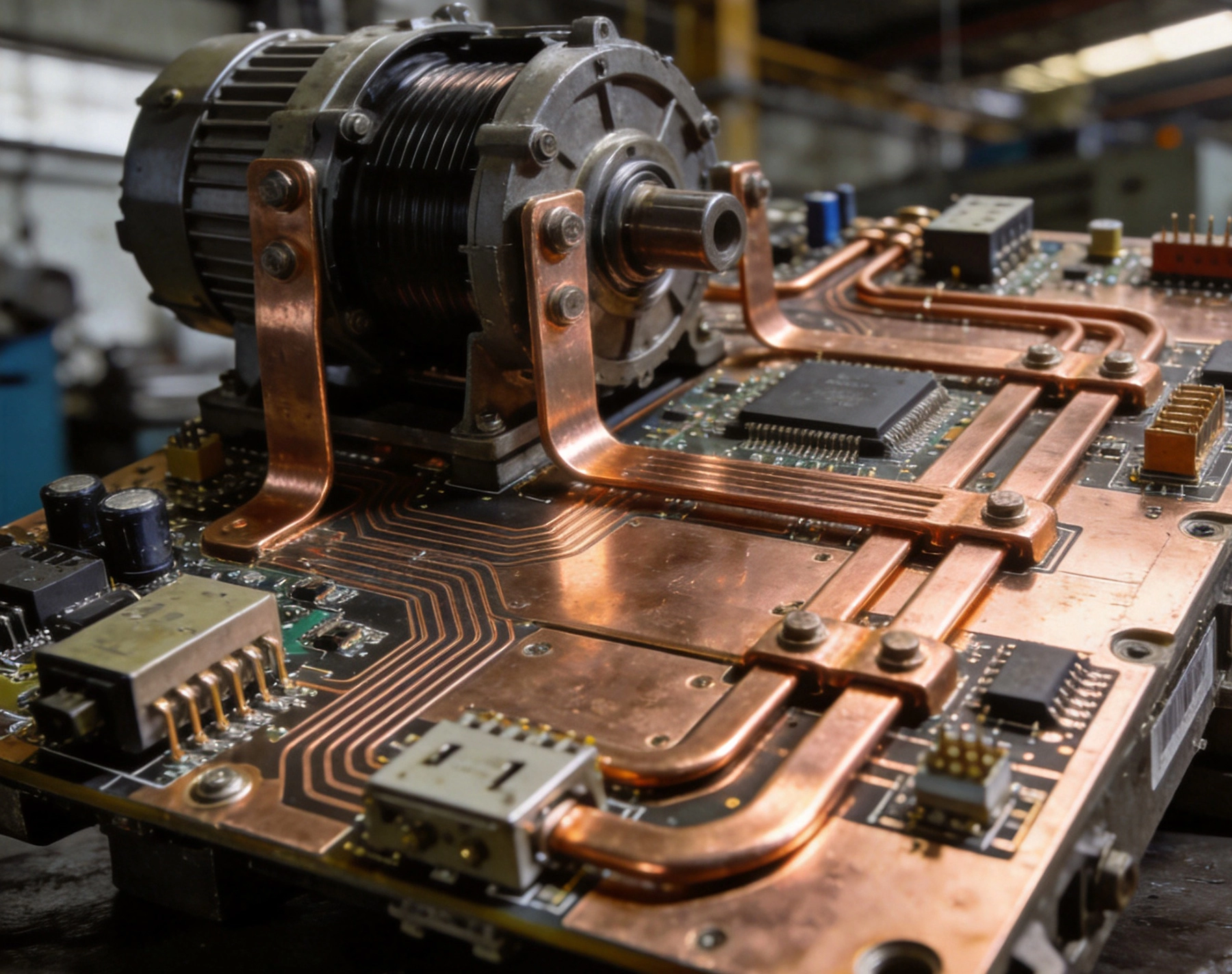
The copper weight of a PCB refers to the thickness of the copper foil used for traces and planes, expressed in ounces per square foot (oz/ft²). Standard PCB construction uses 1 oz copper (approximately 35 microns or 1.4 mils thick). Heavy copper refers to constructions of 3 oz, 4 oz, 6 oz, or even 10 oz and higher. At these thicknesses, the electrical and thermal characteristics change dramatically, enabling design approaches that would be impossible with standard copper.
The Ipc Standards define heavy copper as 3 oz/ft² or greater, though some manufacturers consider anything above 2 oz to be heavy copper. Regardless of the exact threshold, the principle remains the same: thicker copper carries more current with less temperature rise, but requires specialized fabrication processes to achieve reliable results.
The relationship between trace width, copper thickness, and current capacity follows predictable thermal physics. A 100-mil-wide trace in 1 oz copper carrying 10 amps might rise 30°C above ambient. The same trace in 4 oz copper rises only 10°C. This four-fold improvement in thermal performance directly translates to either narrower traces for the same current or higher current capacity for the same trace width.
IPC-2152 provides updated guidance for current-carrying capacity calculations that accounts for Thermal Conductivity through the PCB stackup, surface conditions, and other factors previously ignored in older standards. Designers working with heavy copper should use IPC-2152 charts or simulation tools to size traces appropriately for their specific thermal environment.
Heavy copper PCB Fabrication differs significantly from standard processes. The additional copper thickness affects etching, plating, and lamination in ways that require process adjustments:
Not all PCB manufacturers have experience with heavy copper. Working with an experienced provider ensures these process adjustments are handled correctly, avoiding reliability issues that could emerge from improper fabrication.
Motor drives convert electrical energy with moderate efficiency—typically 95% to 98% for modern inverters. The 2% to 5% lost as heat must be removed from the system to prevent component failures. In high-power motor drives handling tens to hundreds of kilowatts, heat generation per square inch of PCB surface becomes significant. Heavy copper provides critical Thermal Management capabilities that directly improve reliability.
Heavy copper internal planes serve dual purposes: they provide low-impedance current paths and distribute heat from hot spots to cooler areas of the board. A 4 oz or 6 oz internal plane has substantially greater Thermal Conductivity than the Fr-4 Laminate surrounding it, effectively spreading heat across the board before it reaches the surface where convection removes it.
For motor drive applications, placing heavy copper planes adjacent to power semiconductor locations creates a thermal path that conducts heat away from the junction and distributes it before it creates localized hotspots. This spreading reduces the temperature gradient across the board and keeps all components within their rated temperature range.
Thermal Vias connecting power components to internal planes dramatically improve heat removal when heavy copper is used. Standard thermal via arrays remain effective, but heavy copper construction amplifies their benefit by providing more copper volume to conduct heat and spread it through the internal layers.
Via-in-pad construction—where vias are placed within the thermal pad of surface-mount power semiconductors—provides the most direct thermal path from the device to internal planes. With heavy copper planes, the thermal resistance from junction to ambient drops substantially, enabling higher power dissipation without junction temperature violations.
Heavy copper construction can reduce or eliminate the need for external heatsinks in moderate-power motor drives. While dedicated heatsinks provide superior heat removal, they add cost, assembly complexity, and mechanical considerations. Using heavy copper to achieve adequate thermal performance simplifies the design, reduces part count, and improves manufacturing yield.
The trade-off depends on the specific application. A 5 kW motor drive might achieve adequate thermal performance with heavy copper alone, while a 100 kW drive may still require dedicated heatsinks. Understanding this trade-off early in the design process helps define the appropriate copper weight specification.
Beyond Thermal Management, heavy copper provides electrical advantages that affect motor drive performance and reliability.
Higher copper weight means lower trace resistance. At DC or low frequencies, this reduction is straightforward—a 4 oz trace has roughly one-fourth the resistance of a 1 oz trace of the same width. At the switching frequencies present in motor drive inverters (typically 5 kHz to 20 kHz), skin effect causes current to concentrate near the conductor surface, partially negating the benefit of additional copper thickness.
However, even accounting for skin effect, heavy copper reduces overall losses. The lower DC resistance of heavy copper more than compensates for partial skin effect losses, particularly at switching frequencies below 30 kHz where most motor drive inverters operate. The result is improved efficiency and reduced heat generation throughout the operating range.
Motor drive inverters contain high-frequency switching loops where current commutates between the DC bus capacitors and the power semiconductors. The inductance of these loops directly affects voltage overshoot during switching transitions. Heavy copper traces with wider geometry reduce loop inductance, lowering voltage stress on semiconductors and reducing electromagnetic interference.
For a two-ounce versus four-ounce trace of equal width, the inductance reduction is modest—perhaps 10% to 20%. But in the context of high dv/dt switching transitions, even this improvement meaningfully reduces peak voltages and EMI emissions.
In high-current motor drives, voltage drop along power distribution traces can affect control circuit performance if not addressed. Heavy copper reduces voltage drop proportionally to its resistance reduction, improving the accuracy of analog measurements and the stability of gate driver circuits.
Ground bounce—transient voltage differences between local and system ground references—becomes more significant as current levels rise. Heavy copper grounding planes with low impedance minimize ground bounce artifacts that could corrupt analog-to-digital conversions or cause false triggering in protection circuits.
Heavy copper construction provides mechanical advantages that contribute to long-term reliability in the harsh environments where motor drives typically operate.
Industrial motor drives face constant vibration from the motor and surrounding equipment. This vibration stresses solder joints, particularly on heavy components like large capacitors and heatsinks. Heavy copper traces have greater cross-sectional area and improved adhesion to the substrate, distributing mechanical stress more effectively than thin traces.
The improved mechanical robustness of heavy copper construction resists trace fatigue that can develop over years of vibration exposure. While proper mounting and shock absorption at the system level remain important, the PCB itself benefits from heavy copper construction's ability to withstand mechanical challenges.
Motor drives undergo thousands of thermal cycles as they power motors through varying load conditions. Each cycle causes expansion and contraction that stresses solder joints and plated through-holes. The coefficient of thermal expansion (CTE) mismatch between copper and FR-4 creates cumulative stress that can eventually cause fatigue failures.
Heavy copper traces, with their greater cross-sectional area and more robust connection to the substrate through plated barrel walls, resist Thermal Cycling fatigue more effectively than thin copper. Vias in heavy copper boards have thicker barrel walls that withstand cyclic stress without cracking. For applications with frequent thermal cycles, this durability advantage translates directly to longer service life.
Plated through-holes (PTH) carrying high currents in motor drives face stress from both Thermal Cycling and the mechanical effects of current flow. The barrel plating must carry the full circuit current while maintaining reliable connection between layers. Heavy copper fabrication with adequate barrel plating—typically requiring minimum 1 mil (25 microns) plating thickness—ensures reliable current-carrying capacity through the hole.
Heavy copper boards often specify increased plating thickness for via barrels, sometimes 1.5 mils to 2 mils, to provide margin against manufacturing variation and long-term degradation. This additional plating investment pays dividends in reduced field failures and improved service life.
Applying heavy copper effectively requires design practices optimized for Thick Copper construction.
For motor drive applications, a recommended stackup places heavy copper power planes on inner layers where they contribute to both thermal spreading and current distribution. Signal layers remain on outer surfaces with standard geometry for fine-pitch components. A typical four-layer motor drive stackup might use:
Six-layer or eight-layer stackups provide additional routing flexibility while maintaining heavy copper internal planes. The specific configuration depends on the complexity of control circuitry and the current levels the board must handle.
With heavy copper, trace widths can be optimized based on current requirements rather than manufacturing minimums. A motor drive carrying 50 amps on a bus bar might use 500-mil-wide traces in 4 oz copper rather than 1000-mil traces in 2 oz copper, saving board space for other components.
Thermal relief patterns around component pads must be scaled appropriately for heavy copper. Standard thermal reliefs designed for 1 oz copper may be insufficient for heavy copper planes; larger spoke widths or additional spokes maintain adequate solderability during assembly while preserving the current-carrying benefits of heavy copper.
Power semiconductors with exposed thermal pads—MOSFETs, IGBTs, and motor drive ICs—benefit significantly from heavy copper pads connected to internal planes. The thermal path from junction through the package thermal pad, through the solder joint, to the PCB copper, and finally to internal planes improves substantially with heavy copper construction.
For through-hole power components like bulk capacitors and inductors, heavy copper barrel plating and large pad sizes ensure reliable connections that survive thermal cycling. Solder fillet inspection becomes easier with larger pads, improving Quality Control during manufacturing.
For the highest current levels, heavy copper alone may be insufficient. External bus bars—solid copper bars bolted or soldered to the PCB—provide additional current-carrying capacity while keeping the board itself manageable in size. The interface between bus bars and PCB requires careful design to ensure reliable connection under thermal cycling and mechanical vibration.
Soldering bus bars directly to PCB terminations works well for moderate currents where the thermal mass of the connection provides adequate reliability. For higher currents or demanding environments, bolted connections with star washers and appropriate torque specifications ensure long-term reliability.
Designing for heavy copper requires awareness of manufacturing capabilities and constraints that affect producibility and cost.
Heavy copper fabrication has minimum trace width and spacing requirements that differ from standard boards. While 5-mil traces are routine with 1 oz copper, heavy copper boards may require 10-mil to 15-mil minimum traces for reliable fabrication. These constraints affect routing density and the overall board size required for a given circuit.
Understanding manufacturer capabilities early in the design process prevents layout work that cannot be manufactured. Most heavy copper specialists can provide design guidelines specific to their process capabilities.
Heavy copper fabrication typically carries higher tooling and setup costs than standard boards due to the specialized process adjustments required. These costs are amortized across the order quantity, making heavy copper more economical for higher volumes. For prototype quantities, the setup cost per board can be significant; for production runs of hundreds or thousands, the per-board impact diminishes.
When evaluating heavy copper cost, compare the total cost including PCB Fabrication, assembly (which may benefit from simpler thermal management), and any external components like heatsinks that might be eliminated. Heavy copper at higher board cost may reduce total system cost by simplifying thermal management and improving reliability.
Not all PCB manufacturers have the process capability or experience to produce reliable heavy copper boards. When selecting a supplier, consider:
A manufacturer with specific heavy copper experience can provide design guidance that improves producibility and reliability, turning their expertise into a design resource that benefits your project.
Heavy copper solutions appear across the range of motor drive applications, from compact servo drives to large industrial inverters.
Modern servo amplifiers in robotics and automation systems typically handle 10 A to 50 A per axis. Heavy copper construction enables these compact units to achieve high power density without bulky heatsinks or external cooling. A typical three-axis servo drive might use 3 oz copper on internal planes to handle bus currents of 30 A to 50 A while maintaining the compact form factor required for integration into robot arms and automated equipment.
Industrial variable frequency drives (VFDs) for pumps, fans, and compressors range from 5 kW to 500 kW and beyond. The PCB-intensive portion—the control and gating circuitry—typically handles 100 A to 500 A, requiring heavy copper for reliable power distribution. Heavy copper bus bars integrated into the PCB construction distribute current from the DC bus capacitors to the inverter IGBTs with minimal losses and excellent thermal performance.
EV traction inverters operating at 400 V to 800 V with currents exceeding 300 A require heavy copper construction throughout the power stage. The PCB between the DC link capacitors and the motor phases carries hundreds of amps that demand wide traces in Thick Copper. Heavy copper combined with advanced thermal management techniques enables these high-power densities in automotive-qualified packages.
Renewable energy inverters face the additional challenge of highly variable load conditions as wind speed or solar irradiance changes. Heavy copper construction provides the thermal margin to handle peak output conditions while maintaining reliability through the thousands of thermal cycles these systems experience over their 20+ year service life.
For a 30-amp motor drive on an outer layer with 20°C temperature rise, approximately 300 mils of trace width in 3 oz copper provides adequate current capacity. Using 2 oz copper, the same trace would need to be about 500 mils wide. Inner layers with thermal relief to planes can carry more current per unit width due to improved heat spreading through adjacent copper planes. Use IPC-2152 charts or thermal simulation to size traces precisely for your specific stackup and thermal environment.
Yes, most surface finishes work with heavy copper. HASL, ENIG, immersion silver, and OSP are all compatible with heavy copper construction. The heavier copper may affect HASL coverage, potentially creating slightly less uniform coating in deep features, but this rarely affects solderability. ENIG provides the most consistent finish across heavy copper boards due to the uniform thickness of the Plating Process.
Heavy copper primarily affects the thermal mass of the assembly. Components heat more slowly during reflow due to the additional copper acting as a heat sink. Reflow profiles may need adjustment with longer preheat times to bring the entire board to reflow temperature uniformly. Otherwise, standard Smt Assembly processes work well with heavy copper boards. Hand soldering may be more challenging due to the copper's thermal conductivity drawing heat away from the joint.
Heavy copper boards carry higher per-board fabrication costs due to increased material consumption and process time. However, the total system cost may be lower when heavy copper enables simpler thermal management, reduces external component count, or improves reliability enough to reduce field failure costs. For high-current motor drive applications, heavy copper is typically the most cost-effective approach compared to alternatives like external bus bars or parallel standard-copper boards.
Standard PCB shops typically handle up to 3 oz or 4 oz copper. Heavy copper specialists can produce boards with 6 oz, 8 oz, 10 oz, or even heavier copper weights. Above 6 oz, the fabrication process requires more specialized equipment and careful process control. For very high current applications exceeding what even heavy copper can accommodate, external bus bars or laminated bus bar construction may be more practical than further increasing PCB copper weight.
Heavy Copper Pcb solutions provide substantial benefits for motor drive applications where current levels, thermal management, and long-term reliability are paramount. By selecting appropriate copper weights—typically 3 oz to 6 oz for motor drive applications—designers achieve improved thermal performance, reduced conduction losses, and enhanced mechanical durability that directly translates to better field reliability.
The design techniques for heavy copper—optimized stackup configuration, scaled trace geometry, appropriate thermal relief patterns, and proper component pad design—require understanding both the electrical requirements and the manufacturing constraints of thick copper construction. Working with an experienced PCB manufacturer early in the design process ensures the design is optimized for producibility and cost-effectiveness.
While heavy copper carries higher fabrication costs than standard boards, the total system benefits often justify the investment. Reduced thermal management complexity, improved reliability through thermal cycling resistance, and enhanced current distribution all contribute to motor drives that perform better and last longer in demanding applications.
For engineers designing motor drives for Industrial Automation, electric vehicles, renewable energy, or any high-power application, heavy Copper Pcb solutions provide a proven path to reliable, high-performance designs that meet the demanding requirements of modern power electronics.
Ready to explore heavy copper solutions for your motor drive design? Connect with an engineering team experienced in power electronics Pcb Design to evaluate the optimal approach for your specific current, thermal, and reliability requirements.

Designing High-Frequency PCBs for Industrial 5G and IoT ApplicationsJune/26/2026
Understanding Metal Core PCBs (MCPCB) for Superior Thermal ManagementJuly/13/2026

Cost-Effective Industrial PCB Solutions for IoT ApplicationsSeptember/11/2026
Heavy Copper PCBs: The Solution for High-Current Industrial ApplicationsJune/18/2026
Rogers vs. PTFE: Comparing Materials for High-Frequency SolutionsSeptember/17/2026

Innovative Industrial PCB Solutions for Renewable Energy SystemsAugust/10/2026

Innovative Industrial PCB Solutions for Renewable Energy SystemsAugust/11/2026

End-to-End Industrial PCB Solutions: From Design to DeliveryJuly/08/2026