Open Nav


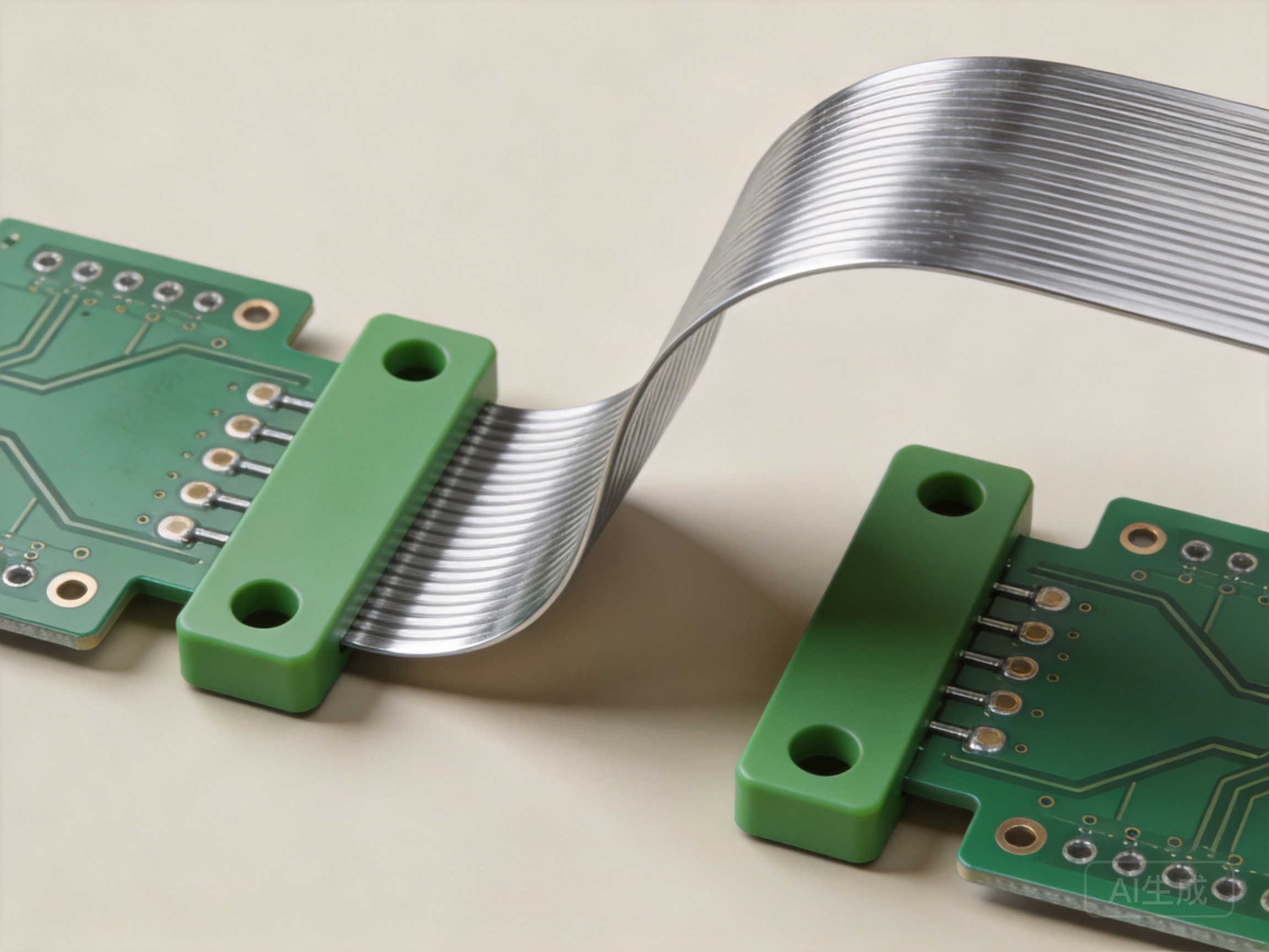
Industrial equipment designers face a persistent tension: make systems smaller and lighter without compromising ruggedness or serviceability. Traditional PCB assemblies use cables, connectors, and daughterboards to fold electronics into available chassis space. That approach works, but it adds weight, introduces failure points, and consumes volume that could be used for other functions.
Rigid-flex Pcb technology offers an alternative. By combining rigid circuit board sections with flexible interconnects in a single assembly, rigid-flex eliminates cables and connectors, reduces overall weight, and enables three-dimensional packaging that conventional boards cannot achieve. For industrial applications where space is tight, weight matters, and reliability is non-negotiable, rigid-flex is increasingly the right choice.
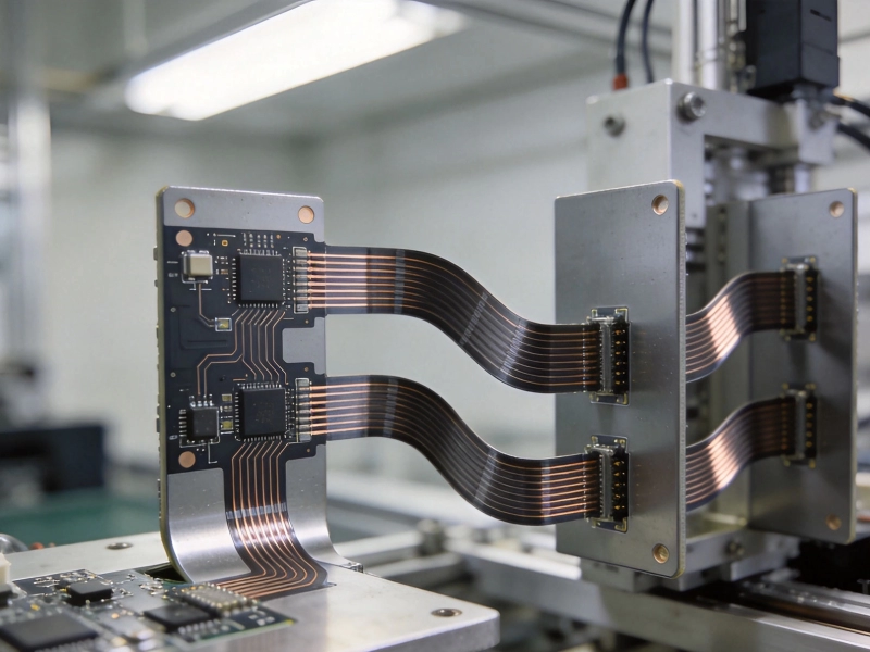
Rigid-flex is a hybrid construction. Rigid sections — typically FR-4 or polyimide-based laminate — provide stable mounting surfaces for components and connectors. Flexible sections — polyimide film with copper traces — provide electrical connections between rigid sections while allowing the assembly to bend, fold, or conform to the enclosure shape.
The key difference from traditional Flexible Circuits is that rigid-flex integrates both structures into a single manufactured unit. The flex sections are not separate cables added during assembly; they are part of the board from the start. This integration eliminates the connector interface between rigid and flexible elements, which is typically the weakest point in a cable-connected assembly.
Rigid-flex boards are manufactured as a single lamination. The flexible layers extend through the rigid sections, providing continuous electrical paths from one rigid area to another. The result is a board that can be folded into a compact shape during assembly, then secured in position for the service life of the product.
Rigid-flex reduces weight in three ways: eliminating connectors, eliminating cables, and reducing board area.
Every connector in a system adds weight. A typical board-to-board connector pair — header and receptacle — weighs several grams. Board-to-cable connectors add similar mass. In a system with multiple interconnects, the connector weight accumulates. Rigid-flex eliminates these connections entirely. The flex section carries signals between rigid areas without a discrete connector interface.
Beyond weight, connector elimination improves reliability. Connectors are mechanical interfaces that can loosen under vibration, corrode in harsh environments, or fail when cables are pulled during assembly or service. Rigid-flex removes that failure mode. The electrical path is continuous from one rigid section to the next.
Traditional cable harnesses use copper conductors insulated by plastic jackets. The insulation adds weight and bulk. A wire bundle that could be replaced by a flex circuit often weighs several times more and requires significantly more cross-sectional area. Rigid-flex compresses that same routing into a thin polyimide film that weighs a fraction of an equivalent cable bundle.
Cable routing also consumes space. Wires need Bend Radius, Strain Relief, and mechanical protection. Flex circuits can be routed through tighter spaces because they are thinner and designed to flex as part of their normal function. This enables packaging options that cables simply cannot support.
Rigid-flex enables three-dimensional packaging. Instead of a single large board laid flat, rigid sections can be folded into a stacked or nested arrangement. This reduces the overall footprint of the Electronics Assembly. The same circuit functions fit into less chassis volume, which allows smaller enclosures, better Thermal Management, or more space for other components.
The space benefits of rigid-flex become clear when looking at specific design scenarios. Here are common industrial applications where rigid-flex delivers measurable packaging advantages.
Portable measurement instruments, handheld scanners, and wearable sensors all operate within severe volume constraints. The electronics must fit into a housing designed around human factors, not board size. Rigid-flex allows the main processor board, sensor boards, and display board to be connected without cable bundles, enabling tighter packaging and thinner overall device profiles.
Industrial systems increasingly use distributed sensor nodes rather than centralized I/O. Each node needs a processor, power conditioning, and sensor interface — but space is limited at the measurement point. Rigid-flex enables the main electronics to be packaged in one location while the sensor interface extends on a flex tail to the actual measurement point. This separation reduces the physical size at the sensor location without sacrificing functionality.
Equipment with moving parts — robotic arms, gantry systems, rotating platforms — poses unique interconnect challenges. Traditional cables flex and fatigue with repeated motion. Rigid-flex designed for dynamic flexing can survive millions of flex cycles, making it suitable for applications where the board itself moves with the mechanism. The flex section carries signals across the moving joint while the rigid sections provide stable mounting for components.
The weight and space benefits are often what drive initial interest in rigid-flex. The reliability advantages are what make engineers glad they chose it.
Connectors are among the most common failure points in Industrial Electronics. Vibration loosens contacts. Temperature cycling causes micro-movement at the pin interface. Moisture and contamination cause corrosion. Mating cycles wear out contact finishes. Rigid-flex removes the board-to-board and board-to-cable connectors that are responsible for a substantial fraction of field failures.
Industrial environments subject electronics to vibration that would be unacceptable in consumer applications. Machine tools, vehicles, and material handling equipment all transmit mechanical energy to the electronics enclosure. Rigid-flex boards are inherently more resistant to vibration because there are no connector interfaces to loosen and no cable bundles to resonate. The flex sections are designed to flex; the rigid sections are securely mounted. The assembly moves as a unit rather than as a collection of separate boards connected by cables.
Connector interfaces create sealing challenges. Each connector penetrates the enclosure wall, requiring a seal that must remain intact across temperature cycles and mechanical stress. Rigid-flex reduces enclosure penetrations. The flex tail can pass through a single sealed opening, reducing the number of potential leak paths. For equipment that must operate in wet, dusty, or corrosive environments, this simplification matters.
Rigid-flex is not a drop-in replacement for traditional board assemblies. It requires different design approaches and different manufacturing considerations.
Flex sections require specific design rules. Traces should be routed perpendicular to the bend direction to minimize stress on the copper. Trace width should be consistent through the bend area — necking down or widening traces at the bend creates stress concentrations. The number of layers in the flex section affects flexibility; fewer layers are more flexible but reduce routing capacity.
Bend Radius is a critical parameter. Flex circuits have minimum bend radius specifications depending on construction and application. Static flex applications — where the board is bent once during assembly and then held in position — can tolerate tighter bends than dynamic flex applications where the board flexes repeatedly in service. Designing for the actual bend radius requirement prevents reliability problems.
The transition between rigid and flex sections requires design attention. The layers that extend from rigid to flex must be properly anchored. Copper features should not extend into the transition zone in a way that creates stress concentration. Good design practice uses larger pads and land patterns at the transition to accommodate the different mechanical properties of the two regions.
Components can be mounted on flex sections, but with constraints. The flex section under a component cannot bend, which may defeat the purpose of the flex. For dynamic flex applications, component placement on flex sections is generally avoided. For static flex applications, components may be placed on flex, but the design must account for the reduced bend capability in the component area.
Rigid-flex boards cost more per unit area than traditional rigid boards. The material cost is higher — polyimide film and specialized laminates are more expensive than standard FR-4. The manufacturing process is more complex, involving Sequential Lamination and careful handling of flex sections. Design iterations are more expensive to tool.
However, the total system cost comparison is more favorable. Eliminating connectors, cables, and associated assembly labor reduces downstream cost. The bill of materials is simpler. Assembly is faster because there are fewer mechanical interfaces to manage. Field failure rates are lower, reducing warranty and service costs. For many industrial applications, the total cost of ownership favors rigid-flex despite the higher board unit cost.
The break-even analysis depends on volume. At low volumes, the tooling cost for rigid-flex dominates, making it harder to justify. At production volumes above a few hundred units, rigid-flex becomes economically competitive for applications where its benefits align with the system requirements.
Rigid-flex is not the right choice for every Industrial Pcb application. It makes sense when:
For applications without these constraints, traditional rigid boards with cable interconnects remain a cost-effective choice. Rigid-flex is an enabling technology for challenging requirements, not a universal replacement.
Rigid-flex manufacturing requires specialized capabilities that not all PCB fabricators possess. When evaluating suppliers, look for experience with industrial applications, evidence of proper flex design support, and capability to handle the specific construction your design requires.
Engage your supplier early in the design process. Rigid-flex design rules vary by manufacturer and by material system. A design that works for one supplier may not be manufacturable by another. Early engagement allows the supplier to review the design, flag potential issues, and suggest alternatives that improve manufacturability and reduce cost.
Request samples and reference designs from your supplier. Seeing how similar applications have been executed gives confidence that the supplier understands the requirements and can deliver a reliable product. A supplier with a portfolio of successful industrial rigid-flex designs is more likely to execute your project correctly.
Weight savings depend on the specific design. Eliminating a typical board-to-board connector pair saves approximately 2 to 5 grams. Eliminating a cable harness can save tens or hundreds of grams depending on the cable count and length. For systems with multiple interconnects, total weight reduction can reach 20 to 30 percent of the Electronics Assembly weight.
Minimum bend radius depends on the flex construction and the application type. For static flex — bent once during assembly — the minimum bend radius is typically 6 times the flex thickness. For dynamic flex — repeated bending in service — the minimum bend radius is typically 10 times the flex thickness or greater. Consult your manufacturer for specific guidance based on the material system and layer count.
Yes, but with limitations. Components on flex prevent the flex section from bending in that area. For static flex applications, this may be acceptable. For dynamic flex applications where repeated bending is required, components on flex are generally avoided. Consider placing components only on rigid sections and using flex sections purely for interconnect routing.
Yes. Rigid-flex is often chosen specifically for vibration resistance. The elimination of connector interfaces removes the most vibration-sensitive failure point in traditional assemblies. The continuous construction from rigid to flex sections distributes mechanical stress more evenly than discrete connectors and cables. Many industrial and aerospace applications use rigid-flex for this reason.
Rigid-flex boards cost more per unit area than standard rigid boards. However, total system cost includes connectors, cables, and assembly labor. In many cases, rigid-flex total system cost is comparable to or lower than traditional approaches because the downstream costs are reduced. The economic case strengthens at higher production volumes where tooling costs are amortized across more units.
An Introduction to HDI Technology for Compact Industrial ElectronicsJune/16/2026

End-to-End Industrial PCB Solutions: From Design to DeliveryJuly/08/2026
Custom Industrial PCB Solutions for the Automotive SectorMay/27/2026
Unlocking Performance with High-Layer Count Industrial PCB SolutionsJune/15/2026
Why Choose Rigid-Flex PCB Solutions for Complex Industrial Assemblies?June/17/2026

Tailored Industrial PCB Solutions for Medical Device ManufacturersJune/12/2026
Manufacturing Challenges in 20+ Layer Industrial PCB SolutionsJuly/09/2026

Designing High-Frequency PCBs for Industrial 5G and IoT ApplicationsJune/26/2026