

Mixed-technology PCB assemblies combining surface mount technology and through-hole components present unique manufacturing challenges. While SMT placement handles the majority of components efficiently, through-hole parts often remain necessary for connectors requiring mechanical robustness, power components needing Heat Dissipation, or components subject to frequent replacement. The soldering approach for these hybrid assemblies requires careful process selection to achieve reliable joints without damaging previously placed SMT parts.
Selective soldering has emerged as the preferred solution for mixed-technology Industrial Pcba, offering precision control that traditional wave soldering cannot match. Understanding these techniques helps engineers Design For Manufacturability and enables production teams to optimize their processes for quality and throughput.
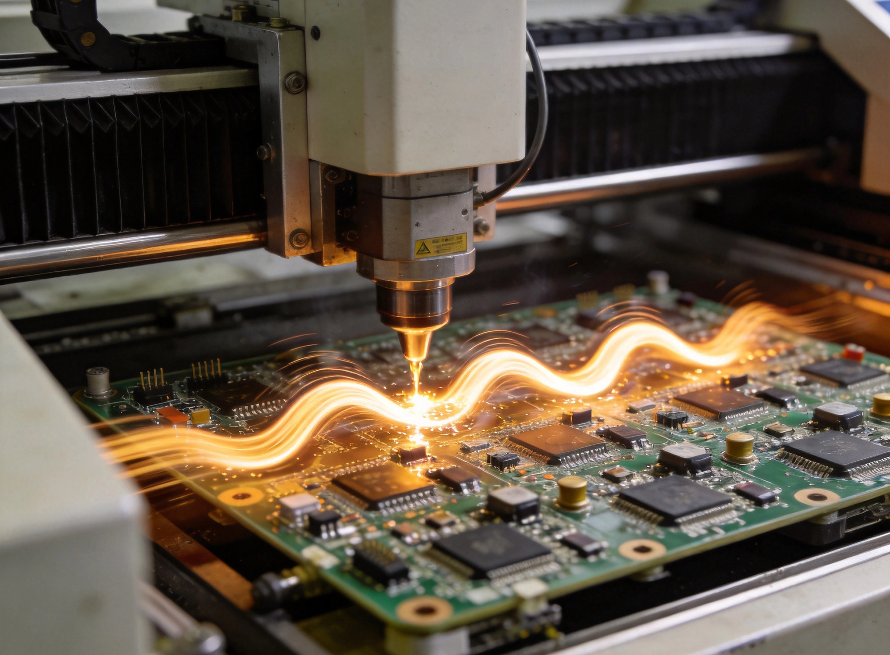
Mixed-technology assemblies integrate components mounted using different attachment methods on the same board. This combination creates manufacturing considerations that single-technology assemblies do not face.
The order in which components are assembled significantly affects manufacturing success:
Process sequencing must consider thermal impact on previously placed components. Wave and selective soldering expose the entire board to solder at 260-265 degrees Celsius, potentially affecting nearby SMT parts.
Not all components tolerate second-side soldering equally:
Designers must identify thermally sensitive components early and plan appropriate accommodations, whether through process modification or component substitution.
Wave soldering represents the original solution for through-hole assembly and remains relevant for high-volume production of compatible boards.
Wave soldering involves passing boards over a pumped wave of molten solder:
The entire bottom surface contacts solder, requiring careful consideration of which components can tolerate this exposure.
Wave soldering presents challenges for mixed-technology boards:
For boards with sensitive SMT components on the bottom side, traditional wave soldering may not be suitable.
Selective soldering addresses wave soldering limitations by targeting specific areas rather than exposing the entire board. This precision enables mixed-technology assembly with improved quality and reduced defect risk.
Modern selective soldering systems consist of multiple integrated modules:
Each module operates under computer control, enabling repeatable process execution across thousands of boards.
Nozzle selection determines the solder application pattern:
Nozzle design continues evolving, with manufacturers developing specialized configurations for specific applications.
Achieving optimal selective soldering results requires attention to multiple process parameters and their interactions.
Flux prepares surfaces for reliable soldering by removing oxides and promoting solder wetting:
Excessive flux creates cleanup requirements and may leave residues that affect long-term reliability.
Thermal Management significantly impacts soldering quality:
Excessive heat damages components and laminates; insufficient heat produces cold or incomplete joints.
The duration and depth of solder contact affect joint quality:
Selective soldering programs define parameters for each soldering location, requiring careful development to achieve consistent quality.
Modern selective soldering systems accept CAD data to streamline programming:
CAD integration reduces programming time but cannot replace process engineering judgment for parameter optimization.
Initial programs require verification and adjustment:
Document optimized parameters for future production runs of the same board design.
Selective soldering defects, while less frequent than wave soldering, still occur. Understanding common issues enables proactive prevention.
Typical selective soldering defects include:
Implement controls to prevent defects before they occur:
Verify soldering quality through appropriate inspection:
Designer decisions significantly impact the ease and success of selective soldering. Early consideration of manufacturing requirements yields better outcomes.
Strategic component placement facilitates reliable soldering:
Through-hole design affects soldering performance:
Design affects thermal behavior during soldering:
Some assemblies require combining multiple soldering methods to achieve optimal results.
The most common hybrid approach:
Boards requiring both sides to have through-hole components:
High-volume production may combine methods:
Sustained quality requires ongoing equipment maintenance and process monitoring.
Regular maintenance ensures consistent performance:
Neglected maintenance leads to increased defects and equipment failures.
Statistical Process Control identifies trends before defects occur:
Selective soldering provides essential capabilities for mixed-technology Industrial Pcba:
Successful mixed-technology assembly requires collaboration between design engineers and manufacturing process teams. Early involvement of process specialists during design yields manufacturable products that meet quality and cost objectives.
Selective soldering is a precision soldering technique that applies solder to specific locations rather than the entire board surface. It is used for mixed-technology assemblies where some components require through-hole soldering but the board contains heat-sensitive parts that cannot survive full wave soldering exposure.
Wave soldering exposes the entire bottom surface of the board to molten solder, while selective soldering targets only specific through-hole locations with programmed precision. Selective soldering provides better control and protects adjacent SMT components from thermal exposure.
Consider selective soldering if your board has through-hole components on the bottom side where surface mount parts would be exposed to wave soldering temperatures, if you have thermally sensitive connectors or components, or if your board requires specific quality standards that demand precise solder application control.
Cycle time depends on the number of through-hole locations requiring soldering, the specific parameters needed for each location, whether components are processed individually or in groups, and the complexity of the program patterns. Larger boards with many through-hole parts may require longer cycle times.
Selective soldering handles most through-hole components effectively. Very large connectors or components with unusual thermal requirements may need special consideration. Process engineers should evaluate component compatibility during program development.
Prevent bridging by optimizing solder contact time, using appropriately sized nozzles, verifying proper flux application, maintaining correct solder pot temperature, and ensuring adequate spacing between adjacent through-hole locations. Regular equipment maintenance also prevents contamination that can contribute to bridging.
SMT vs. Through-Hole: Best Practices for Industrial PCBAJuly/07/2026
The Importance of Component Obsolescence Management in Industrial PCBAAugust/07/2026
X-Ray Inspection: Why It's Vital for Complex Industrial PCBA ProjectsSeptember/26/2026
Industrial PCBA: Navigating the Complexities of Box Build AssemblyJune/09/2026
Manufacturing Processes for Extreme Heavy Copper Industrial PCBsAugust/15/2026
Navigating the Complexities of Box Build AssemblyMay/27/2026
How to Ensure Quality Control in High-Mix Low-Volume Industrial PCBAJuly/21/2026
Minimizing Signal Loss and Crosstalk in High-Speed PCB LayoutsSeptember/01/2026