Open Nav


When your PCB will operate near its thermal limits, standard FR-4 isn't enough. High-tg Materials—the backbone of reliable industrial, automotive, and aerospace electronics—offer the thermal stability your designs need to survive demanding environments. This guide explains everything you need to know about Glass Transition Temperature, when to specify high-Tg, and how to select the right laminate for your application.
The global shift toward lead-free assembly has made High-tg Materials essential rather than optional. Lead-free solder alloys melt at higher temperatures, exposing PCBs to thermal stress that standard materials weren't designed to handle. Add in increasing power densities, tighter miniaturization, and demanding operating environments, and understanding high-Tg materials becomes critical for anyone involved in Pcb Design, procurement, or manufacturing.
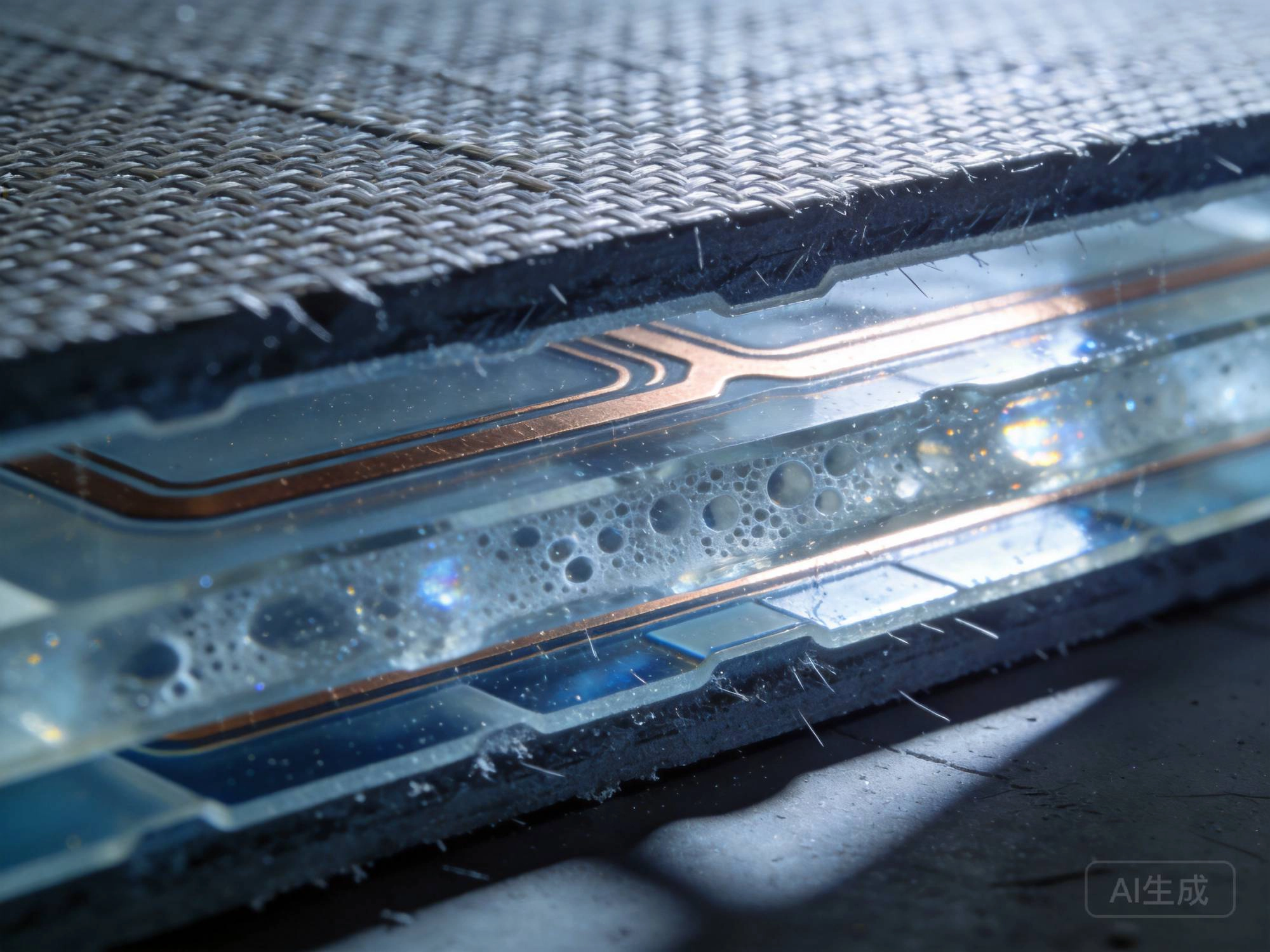
Glass Transition Temperature—expressed in degrees Celsius—is the point at which a polymer transitions from a rigid, glassy state to a softer, rubbery state. For PCB substrates, this transition profoundly affects mechanical and electrical properties.
Below Tg, the substrate is rigid and dimensionally stable. Above Tg, the material softens, its coefficient of thermal expansion (CTE) increases dramatically, and it loses much of its structural integrity. A PCB operated above its Tg risks:
Understanding how substrates behave thermally helps explain why Tg matters so much in industrial applications.
Tg is not the same as thermal decomposition temperature (Td). Td is the point at which the material chemically degrades—typically 50-80°C above Tg for standard epoxies. Think of Tg as the "softening point" and Td as the "burn point." Your operating temperature should stay well below Tg, not approach Td.
Industry best practice recommends keeping maximum operating temperature at least 20°C below Tg. If your board might see 125°C in operation, you need a material with Tg of at least 145°C—and preferably higher to account for thermal gradients and hotspots.
The coefficient of thermal expansion (CTE) measures how much a material expands per degree of temperature increase. PCB substrates have different CTE values in the X-Y plane (in-plane) versus the Z-axis (through thickness). The Z-axis CTE is particularly critical because it determines how much plated through-holes stretch during thermal excursions.
Below Tg, Z-axis expansion is manageable. Above Tg, Z-axis expansion increases 3-5x, creating enormous stress on via barrel plating. This stress causes fatigue cracks that propagate over Thermal Cycling cycles, eventually creating open circuits. High-Tg materials reduce this problem by raising the temperature at which dangerous expansion begins.
Traditional tin-lead solder reflow peaks around 225°C, well below standard FR-4's Tg of 130-140°C. Lead-free SAC305 solder requires peak temperatures of 245-260°C to achieve reliable wetting. At these temperatures, standard FR-4 approaches or exceeds its Tg, causing temporary softening, Z-axis expansion, and dimensional instability during every assembly reflow cycle. High-Tg materials handle this thermal excursion without softening.
High-Tg encompasses a range of materials with different properties, costs, and applications. Understanding the categories helps you specify appropriately.
While not "high-Tg," standard FR-4 sets the baseline. Made from woven E-glass fiberglass with brominated epoxy resin, it offers good electrical properties and cost-effectiveness for controlled environments. Not suitable for lead-free assembly or elevated temperature operation.
Best for: Consumer electronics, office environments, cost-sensitive designs with adequate thermal margin
Enhanced epoxy formulations push Tg into the 150-170°C range while maintaining compatibility with standard FR-4 processing. These materials bridge the gap, handling lead-free assembly without requiring specialty equipment or significantly higher costs.
Best for: Lead-free assembly requirements, automotive under-hood applications, industrial controls with moderate thermal exposure
Advanced epoxy systems achieve Tg values of 170°C and above. These materials offer significantly improved thermal performance while remaining processable using standard PCB Fabrication equipment. Popular choices for demanding industrial applications.
Best for: Industrial Automation, Power Electronics, LED lighting drivers, telecommunications infrastructure
Specialty epoxy systems pushed to higher Tg values, sometimes exceeding 200°C. These materials may require modified processing parameters and typically command premium pricing but offer excellent thermal performance with good electrical properties.
Best for: Aerospace systems, downhole electronics, high-power density designs, military applications
Polyimide substrates—flexible Kapton and rigid polyimide laminates—offer exceptional Thermal Resistance. While more expensive and challenging to process, they provide unmatched performance in extreme temperature applications where other materials fail.
Best for: Aerospace, defense, high-temperature sensors, downhole drilling, any application above 200°C
| Property | Standard FR-4 | Mid-Tg FR-4 | High-tg Fr-4 | Polyimide |
|---|---|---|---|---|
| Tg Range | 130-140°C | 150-170°C | 170-180°C | 250-400°C |
| Typical Td | 320°C | 340°C | 360°C | 500°C+ |
| Z-CTE (below Tg) | 45-65 ppm/°C | 40-55 ppm/°C | 35-50 ppm/°C | 20-40 ppm/°C |
| Dielectric Constant (1MHz) | 4.2-4.5 | 4.0-4.4 | 3.9-4.3 | 3.5-4.2 |
| Loss Tangent (1MHz) | 0.015-0.020 | 0.014-0.018 | 0.012-0.016 | 0.003-0.015 |
| Moisture Absorption | 0.10-0.15% | 0.08-0.12% | 0.05-0.10% | 0.2-0.8% |
| Relative Cost | 1x | 1.2-1.5x | 1.5-2.0x | 5-10x |
| Processability | Standard | Standard | Minor adjustments | Specialized |
Not every application requires high-Tg materials. Specifying unnecessarily expensive materials wastes money, but under-specifying risks field failures. Here are the scenarios where high-Tg becomes essential:
If your products ship to Europe, China, or other markets requiring RoHS compliance, lead-free assembly is mandatory. The higher reflow temperatures of lead-free solder (245-260°C peak) exceed standard FR-4's Tg. High-Tg materials ensure boards survive assembly without Delamination, warpage, or void formation.
Any application where the board will experience sustained temperatures above 100°C—or Thermal Cycling that pushes peak temperatures above 130°C—requires high-Tg. Typical elevated-temperature applications include:
Multi-layer boards with 6+ layers experience more complex thermal profiles during lamination and assembly. Internal layers see extended time at elevated temperatures and are constrained by adjacent layers. High-Tg materials provide the thermal stability needed for reliable multi-layer construction.
High-density interconnect (HDI) boards with Microvias and fine-pitch components (0.4mm pitch BGAs and smaller) are more sensitive to thermal stress. The fine geometry leaves less margin for error—any Z-axis expansion risks cracking microvia barrels. High-Tg materials provide the dimensional stability these demanding designs require.
All PCB substrates absorb some moisture from the environment. High-Tg materials typically absorb less moisture than standard FR-4 because their denser cross-linked polymer structure has fewer sites for water molecules to bind. This matters because moisture:
High-Tg materials' lower moisture absorption improves long-term reliability in humid environments and reduces sensitivity to moisture exposure during assembly and storage.
Standard FR-4's electrical properties degrade significantly above 100°C. Dielectric Constant increases, loss tangent rises, and insulation resistance drops. High-Tg materials maintain stable electrical performance at temperatures where standard materials fail. For high-frequency applications or high-voltage designs, this thermal stability is critical.
The real test of any PCB material isn't a single high-temperature exposure—it's thousands of thermal cycles between temperature extremes. High-Tg materials offer superior resistance to thermal cycling fatigue because their higher glass transition temperature keeps them in the stable glassy state during more of each cycle. Studies show high-Tg materials can extend thermal cycle life by 2-5x compared to standard FR-4 in identical test conditions.
Conductive Anodic Filament (CAF) failure occurs when copper ions migrate along glass fiber interfaces under bias voltage, eventually creating conductive paths between traces. High-Tg materials with better resin-glass interfacial bonding show significantly improved CAF resistance. For high-voltage applications (above 50V) or designs with closely spaced traces, CAF resistance is a key selection criterion.
High-Tg materials can typically be processed on standard PCB Fabrication equipment, but some process adjustments improve yields and quality.
| Process Step | Standard FR-4 | High-tg Fr-4 |
|---|---|---|
| Lamination Temperature | 180°C | 200-220°C |
| Lamination Pressure | 300-400 PSI | 350-450 PSI |
| Press Time | 60-90 min | 75-120 min |
| Drill Parameters | Standard peck cycle | Modified peck, fewer hits |
| Tool Wear | Moderate | Slightly higher |
The PCB laminate market offers numerous high-Tg options from established manufacturers:
For extreme applications, some fabricators work with specialty laminates:
High-Tg materials typically cost 1.5-2x more than standard FR-4, but the total cost of ownership often favors high-Tg when you factor in:
A single field failure in an industrial application can cost 10-100x the material cost difference. If a warranty return requires a service visit to a remote installation, costs escalate rapidly. A 1% improvement in first-pass yield often pays for the material upgrade many times over. The question isn't whether you can afford high-Tg—it's whether you can afford not to use it.
High-Tg materials behave differently during lamination than standard FR-4. Work with your fabricator to develop an appropriate stack-up:
High-Tg materials typically have lower Thermal Conductivity than metals, so Thermal Management design becomes even more important:
High-Tg materials' reduced Z-axis expansion helps vias survive thermal cycling, but good via design still matters:
Verifying that high-Tg materials meet specifications requires appropriate testing:
Here's a practical decision framework for selecting the right material:
| Application Scenario | Recommended Material | Rationale |
|---|---|---|
| Consumer electronics, lead-free assembly | Mid-Tg FR-4 (150-160°C) | Cost-effective for lead-free, adequate margin |
| Automotive, under-hood (125°C) | High-Tg FR-4 (170-180°C) | 20°C margin above operating temp, lead-free compatible |
| Industrial motor drive | High-Tg FR-4 (180°C) | Thermal cycling resistance, CAF resistance |
| LED lighting, enclosed luminaire | High-Tg FR-4 (170-180°C) | Elevated ambient temp, lead-free often required |
| Downhole instrumentation (150°C+) | High-performance or polyimide | Exceeds standard high-Tg capability |
| Aerospace, defense | Polyimide or spec ceramic | Highest reliability, widest temperature range |
Laminate manufacturers publish detailed datasheets with comprehensive property data, but interpreting that data in the context of your specific application requires experience. Reputable PCB fabricators work with multiple material families daily and can recommend appropriate options based on your requirements, volume, and budget. A good fabricator's engineering team is an invaluable resource—use them early in your design process.
High-Tg materials are not an luxury—they're an essential tool for modern Pcb Design. Understanding when and why to specify them helps you build reliable products that survive their intended service life. Whether you're designing consumer electronics that must survive lead-free assembly or industrial systems that must operate for decades in demanding environments, the right material choice makes the difference between success and failure.
Most industry guidelines recommend a minimum Tg of 150°C for lead-free assembly, with 170°C or higher preferred. The higher peak temperatures of lead-free reflow (245-260°C) approach or exceed standard FR-4's Tg, risking board softening. High-Tg materials provide thermal margin that prevents assembly defects and improves long-term reliability.
While technically possible, mixing different material families in multi-layer boards is generally not recommended. Different CTE values, resin systems, and processing requirements create interlaminar stress and potential delamination risks. If cost optimization is critical, consider using high-Tg materials only for the outer layers where thermal stress is highest, or use a consistent high-Tg system throughout.
Not necessarily. While some high-Tg formulations offer improved electrical properties (lower loss tangent, more stable dielectric constant), thermal performance and electrical performance are separate material characteristics. High-frequency applications may actually perform better with specialty materials (like Rogers laminates) that are optimized for RF performance rather than thermal performance. Evaluate electrical and thermal requirements independently.
Material cost increases approximately 1.5-2x for high-Tg FR-4 compared to standard FR-4. Processing costs may increase slightly due to higher lamination temperatures and times. However, total board cost typically increases only 15-30% because materials are only one component of total cost. For high-volume production, the per-board premium is often modest compared to the reliability benefits.
Standard FR-4 can often survive lead-free assembly, but the risk of defects increases significantly. Common failure modes include delamination (layers separating), measling (white spots indicating micro-cracking in the weave), warpage (board twisting or bending), and inner-layer separation. Even boards that pass initial inspection may have hidden damage that manifests as field failures months or years later.
High-Tg Pcb Materials represent one of the most important material advances in modern Electronics Manufacturing. As lead-free assembly becomes universal and operating environments grow more demanding, understanding these materials transitions from nice-to-know to essential knowledge.
The key takeaways are straightforward: Tg defines the temperature at which your board's substrate softens and loses mechanical stability. High-Tg materials provide the thermal margin necessary for lead-free assembly and elevated-temperature operation. Selecting the right Tg for your application—neither over-specifying nor under-specifying—optimizes cost while ensuring reliability.
Work with your material suppliers and PCB fabricators early in the design process. Share your thermal requirements, assembly method (lead-free or leaded), operating environment, and reliability expectations. Their expertise helps you navigate the Material Selection process and choose the right solution for your specific needs.
In Industrial Electronics, reliability is not optional. The boards you design today will operate in equipment that may be difficult or impossible to service for years or decades. Making the right material choices now prevents failures, protects your reputation, and keeps your customers' systems running reliably.
How to Select Industrial PCB Materials for High-Voltage ApplicationsSeptember/07/2026
A Comprehensive Guide to High-Tg Materials for Industrial PCBsJune/05/2026
Understanding CTE and Its Impact on Industrial PCB Materials SelectionJuly/18/2026
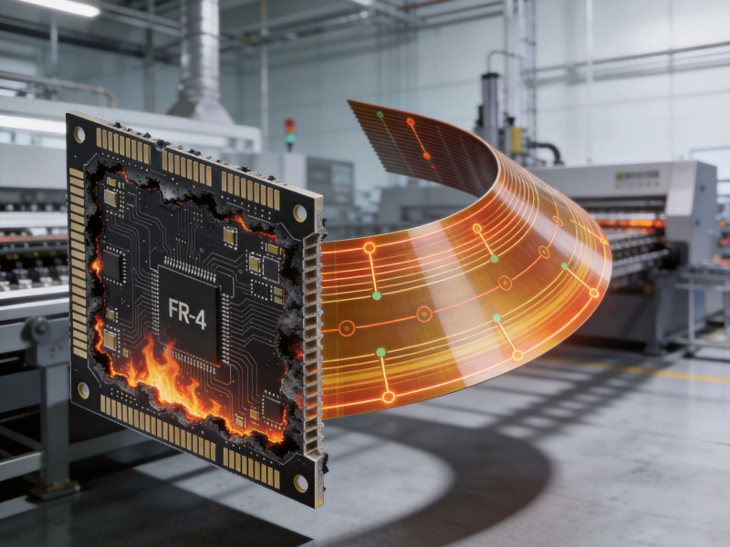
FR-4 vs. Polyimide: Choosing the Right Industrial PCB MaterialsJuly/02/2026
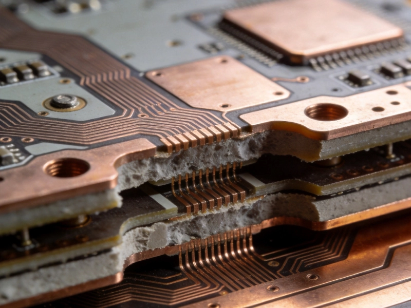
Copper Weight Matters: Optimizing Industrial PCB Materials for Power ElectronicsSeptember/23/2026
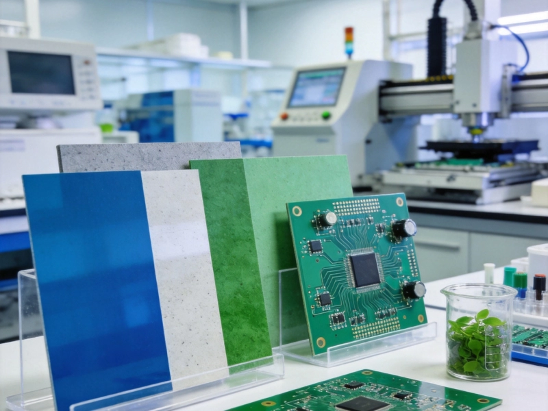
The Rise of Halogen-Free Industrial PCB Materials: Benefits and Trade-offsAugust/06/2026
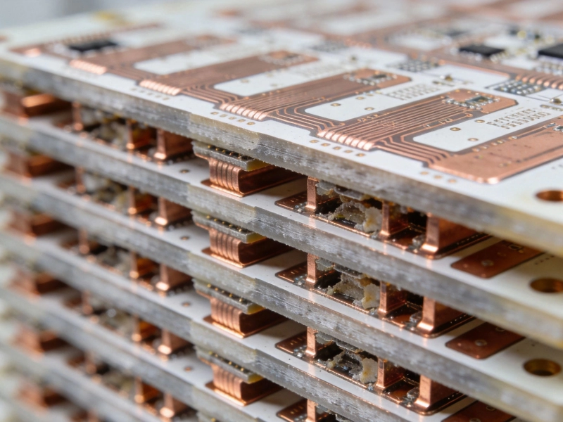
Manufacturing Challenges in 20+ Layer Industrial PCB SolutionsJuly/09/2026
The Impact of Surface Finishes on Industrial PCB Fabrication QualityJuly/16/2026