Open Nav


The automotive industry is undergoing the most profound transformation in its history—and at the heart of that transformation is electronics. From engine management and safety systems to infotainment, autonomous driving, and electric powertrains, modern vehicles depend on printed circuit boards that meet requirements no consumer or industrial product has ever demanded before. Reliability that spans 15 years and 150,000 miles. Performance under extreme temperature ranges. Zero tolerance for failure in safety-critical systems. And production volumes that demand manufacturing excellence at scale.
This is the world of automotive PCB solutions—where the stakes are highest, the standards are strictest, and the engineering challenges are most demanding.

A PCB for an automotive application is not simply a standard industrial PCB with tighter tolerances. The automotive environment creates a unique set of stresses that require fundamentally different approaches to design, materials, manufacturing, and testing.
Temperature extremes: Under-hood electronics face temperatures from -40°C during cold starts to +150°C near the engine block. Board materials must maintain mechanical and electrical integrity across this range, repeatedly, for the life of the vehicle.
Vibration and mechanical stress: Vehicles vibrate continuously. Road conditions introduce shock loads. PCBs must be designed to withstand cyclic fatigue in solder joints, component terminations, and board laminates over hundreds of thousands of miles of operation.
Humidity and contamination: Automotive electronics face condensation, water splash, road salt, and fuel contamination. Sealing, conformal coating, and material selection must account for exposure to moisture and corrosive environments.
Long lifetime requirements: Automotive electronics must operate reliably for 15+ years in some applications. This means accelerated life testing, extensive qualification testing, and design margins that account for component aging over the vehicle's service life.
Safety-critical reliability: Electronic stability control, anti-lock braking, airbags, and autonomous driving systems require failure rates approaching zero for safety-critical functions. The cost of failure is measured in human lives, not just warranty claims.
Regulatory compliance: Automotive electronics must meet international standards for safety, emissions, and electromagnetic compatibility. The regulatory landscape varies by market but demands rigorous documentation, testing, and certification.
The Automotive Electronics Council (AEC) qualification standards define the testing requirements that components and boards must pass to be considered automotive-grade. These are not suggestions—they are the baseline requirements for any PCB intended for automotive safety-critical applications.
AEC-Q100: Integrated circuit qualification. Defines stress test requirements for ICs including temperature cycling, high-temperature operating life, humidity bias, electrostatic discharge, and mechanical integrity.
AEC-Q101: Discrete semiconductor qualification. Covers transistors, diodes, and other discrete components with requirements for temperature cycling, power cycling, and humidity tolerance.
AEC-Q102: Optoelectronic semiconductor qualification. Covers LEDs and photodiodes used in automotive lighting and sensing applications.
AEC-Q104: Multichip module qualification. Covers multi-die components that combine multiple ICs or passive components in a single package.
AEC-Q200: Passive component qualification. Covers resistors, capacitors, inductors, and other passive components with requirements for stress testing specific to each component type.
For PCBs specifically, while there is no single AEC-Q specification dedicated solely to bare boards, the PCB must be designed and manufactured to support the qualification of the complete assembly to the above standards. This means the board itself must meet IPC Class 3 (the highest reliability class for electronic assemblies) and must be fabricated to specifications that ensure the assembly can pass AEC-Q stress testing.
The IPC standards define the quality requirements for electronic assemblies and the workmanship standards that manufacturers must meet:
IPC-A-600: Acceptability of printed boards. Defines the acceptance criteria for bare PCBs including surface conditions, conductors, holes, and laminate defects.
IPC-A-610: Acceptability of electronic assemblies. Defines the acceptance criteria for assembled electronic equipment including component placement, soldering, and inspection requirements.
IPC-6012: Qualification and performance specification for rigid printed boards. Defines the qualification requirements and performance parameters for rigid PCB fabrication.
IPC-6012DA: Automotive applications addendum to IPC-6012. This document specifically addresses the additional requirements for automotive-grade rigid printed boards, including extended temperature range, vibration testing, and enhanced documentation requirements.
IPC-7711/7721: Rework and repair of electronic assemblies. For automotive production, rework procedures must be documented, controlled, and verified. Uncontrolled rework is not acceptable in automotive quality systems.
IATF 16949 is the quality management system standard for the automotive industry. It supersedes ISO/TS 16949 and defines the requirements for organizations that design, develop, produce, install, and service automotive-related products.
For a PCB manufacturer, IATF 16949 certification means:
Documented process control with statistical evidence of capability. Production part approval process (PPAP) submissions that prove the manufacturing process can produce parts meeting specifications consistently. Advanced product quality planning (APQP) that defines the development process from concept through production launch. Traceability from incoming materials to finished products with serial number tracking. And regular internal and external audits that verify compliance with documented procedures.
Without IATF 16949 certification, a PCB manufacturer cannot supply directly to most automotive OEMs or Tier 1 suppliers.
Thermal management is arguably the most critical design consideration for automotive PCBs. Heat comes from multiple sources: the components on the board, the environment outside the enclosure, and heat conducted through connectors and mounting points from nearby engine components.
Effective thermal design starts with material selection. The glass transition temperature (Tg) of the board laminate must be high enough to maintain mechanical integrity at maximum operating temperature. For under-hood applications, Tg values of 150°C or higher are often required. High-Tg materials like Isola Tg150, Shengyi S1000H, and Panasonic R-1566W are commonly specified for demanding automotive applications.
Thermal conductivity of the dielectric material affects how efficiently heat spreads across the board. Standard FR-4 has thermal conductivity around 0.3 W/mK. For high-power applications, metal-core substrates (IMS boards) with thermal conductivities of 1-5 W/mK or higher provide much more effective heat spreading.
Via design also affects thermal performance. Thermal vias placed beneath heat-generating components conduct heat from the component side to the ground plane or heat sink on the opposite side of the board. Via-in-pad construction—where vias are placed directly in component pads—provides the best thermal connection but requires controlled manufacturing processes to avoid solder voiding.
Standard FR-4 is adequate for many automotive interior applications—infotainment systems, instrument clusters, and comfort electronics operate in benign environments. But for under-hood, powertrain, and safety applications, higher-performance materials are required:
High-Tg FR-4: Glass transition temperatures of 150-170°C provide improved thermal resistance. Suitable for under-dash and moderate temperature environments.
Polyimide (PI): Operating temperatures up to 260°C with excellent mechanical stability. Used in extreme temperature environments and in applications with high vibration. More expensive than FR-4 but provides superior thermal performance.
Flexible and rigid-flex circuits: For applications with space constraints or three-dimensional routing requirements, flexible circuits (FPC) and rigid-flex constructions allow routing around complex geometries. Automotive-grade flexible circuits use polyimide base materials with special adhesive systems designed for long-term temperature cycling.
Metal-core substrates (IMS): For high-power LED lighting, motor drives, and power conversion applications. Metal cores—typically aluminum or copper—provide efficient heat spreading. IMS boards can reduce component junction temperatures by 20-40°C compared to standard FR-4.
halogen-free materials: Many automotive OEMs now require halogen-free board materials for environmental compliance. These materials meet VW specifications for low-halogen content and produce reduced toxic gases in fire conditions.
Modern vehicles contain an unprecedented density of electronic systems that must coexist without mutual interference. Automotive EMC requirements are among the most demanding in any industry:
CISPR 25: Radio disturbance characteristics of vehicles and components. Defines the limits for radiated and conducted emissions from automotive electronics.
ISO 11452: Component-level immunity testing for electrical disturbances from narrowband radiated electromagnetic energy.
ISO 7637: Electrical disturbances from conduction and coupling. Tests the immunity of automotive electronics to transient disturbances on power supply lines.
PCB designers must address signal integrity through careful stackup design, controlled impedance routing for high-speed signals, proper grounding and shielding, and attention to the return current path. Automotive CAN, LIN, FlexRay, Automotive Ethernet, and USB 2.0/3.0 all require specific impedance tolerances and routing constraints.
Automotive electronics is trending toward miniaturization—just like consumer electronics—but miniaturization introduces reliability risks that must be carefully managed. Smaller component packages have smaller solder joints, which are more susceptible to vibration and thermal cycling fatigue. Densely packed boards create thermal management challenges and make visual inspection more difficult.
The automotive industry's response has been to require rigorous qualification testing for any new technology or process introduction. Automotive PCB manufacturers must prove that miniaturization doesn't compromise reliability through extended temperature cycling, vibration testing, and thermal shock testing that simulates 15 years of field service in accelerated time.
Automotive PCB manufacturing requires process control that goes far beyond standard IPC Class 3 requirements. Every process parameter must be documented, monitored, and proven capable. This includes drill parameters (spindle speed, feed rate, hit count), plating bath chemistry (metal concentration, pH, temperature), lamination cycles (temperature, pressure, time), and surface finish process parameters.
Statistical process control (SPC) data must be collected and maintained for key characteristics. Critical dimensions—hole diameters, trace widths, dielectric thickness—must be measured regularly, and process capability indices (Cpk) must meet or exceed the values specified in the quality plan. Typical automotive requirements are Cpk ≥ 1.33 for critical characteristics and Cpk ≥ 1.67 for safety-critical characteristics.
Surface finish selection for automotive PCBs must consider multiple factors: solderability, shelf life, compatibility with assembly processes, environmental compliance, and cost:
ENIG (Electroless Nickel Immersion Gold): Provides excellent flatness for fine-pitch components and long shelf life. The gold layer protects the nickel barrier from oxidation. Widely used in automotive infotainment and communication electronics. Main concern is black pad syndrome (nickel corrosion), which requires strict process control and bath monitoring.
OSP (Organic Solderability Preservative): Environmentally friendly with good solderability when used within shelf life limits. Less expensive than ENIG but provides no barrier protection and degrades with multiple thermal cycles. Suitable for boards with moderate shelf life and assembly schedules.
Immersion Silver: Good solderability with moderate cost. Flat surface suitable for fine-pitch components. Sensitive to handling and storage conditions. Silver migration can be a concern in high-humidity environments if not properly controlled.
Lead-free HASL: Provides good solderability and self-leveling that fills surface irregularities. Less flat than ENIG or OSP, making it less suitable for fine-pitch components. Lead-free HASL (SAC305 alloy) is required for RoHS compliance. Higher solder paste volume requirements can be a consideration.
Automotive PCB manufacturers use multiple inspection and test methods to ensure quality:
Automated Optical Inspection (AOI): Performed after fabrication and after assembly. Detects surface defects, component placement errors, and solder defects. 3D AOI with structured lighting provides more reliable detection of subtle defects than 2D inspection.
X-ray Inspection: Essential for inspecting hidden solder joints—BGAs, QFNs, and through-hole components. X-ray reveals voiding in BGA solder joints, alignment of buried vias, and quality of press-fit connector terminations.
In-Circuit Test (ICT): Verifies component presence, value, and connectivity. Automotive PCBs with high reliability requirements typically require ICT with coverage exceeding 95% of nodes.
Flying Probe Testing: For low-to-medium volume boards, flying probe provides the same node coverage as ICT without fixture investment. For prototype and pre-production boards, flying probe is typically the most cost-effective test approach.
Functional Test: Boards or assemblies that incorporate microprocessors, communication interfaces, or other complex functions require functional test programs that verify correct operation under simulated automotive conditions.
Electric vehicles are driving demand for PCBs that handle power levels far beyond traditional automotive applications. Traction inverters, DC-DC converters, onboard chargers, and battery management systems all contain PCBs that must manage high currents, handle significant heat dissipation, and maintain reliability over the vehicle's life.
Power modules for EVs increasingly use substrates like direct bonded copper (DBC) and active metal brazed (AMB) substrates that provide superior thermal conductivity and current-carrying capacity. These substrates enable power densities that would be impossible with conventional PCB technology.
ADAS sensors—radar, LiDAR, cameras, and ultrasonic sensors—require PCBs that combine high-frequency signal integrity, thermal management for processing electronics, and miniaturization for integration into space-constrained sensor packages.
77 GHz automotive radar PCBs require controlled impedance substrates with very tight tolerances and low loss characteristics at high frequencies. Materials like Rogers RO3003 and RO4003 are commonly specified for radar applications. The millimeter-wave frequencies used in automotive radar push the limits of conventional PCB manufacturing and require specialized expertise.
LED lighting systems have become standard across all automotive lighting applications, from headlights to taillights to interior illumination. LED PCBs must manage heat effectively to maintain LED junction temperatures within specification—thermal management directly affects LED lifespan and light output. Metal-core IMS boards are typically used for high-power LED applications.
The introduction of 5G cellular connectivity in vehicles requires PCBs that support even higher frequencies than existing automotive applications. The sub-6 GHz and mmWave bands used by 5G require low-loss materials, precise controlled impedance, and manufacturing processes that maintain tolerances at dimensions that challenge conventional PCB capability.
Choosing the right PCB manufacturer for automotive applications is a strategic decision that affects product quality, supply chain reliability, and long-term cost of ownership. Key criteria include:
Certifications: IATF 16949 certification is the minimum requirement. Additional certifications—such as ISO 14001 for environmental management and UL certification for safety—indicate broader organizational capability.
Automotive experience: Years of automotive production experience and familiar relationships with automotive Tier 1 suppliers and OEMs. Experience with specific automotive applications—safety systems, powertrain, infotainment, ADAS—demonstrates capability in the relevant technology area.
Quality systems: Documented quality plans, statistical process control programs, incoming inspection procedures, and outgoing test requirements. Capability data (Cpk reports) for critical characteristics. Traceability systems that can track materials and processes from lot level to individual board serial number.
Engineering support: Design For Manufacturing review that identifies potential production issues before fabrication begins. Material selection guidance based on application requirements. Stackup design support for controlled impedance boards. Manufacturing expertise that can suggest cost-effective alternatives when design requirements conflict with manufacturing capability.
Supply chain stability: Relationships with Tier 1 laminate and copper foil suppliers. Long-term material supply agreements that protect against commodity shortages. Multiple qualified sources for critical materials.
Financial stability: The automotive industry demands long-term supply commitments. A PCB supplier's financial stability affects their ability to invest in equipment, maintain inventory, and support multi-year product programs.
Automotive PCB costs are higher than standard commercial PCBs—sometimes significantly so. The reasons are straightforward: tighter tolerances require more precise manufacturing processes, more documentation requires more administrative overhead, more testing catches defects before they reach customers but adds cost, higher-quality materials cost more, and process capability data requires investment in measurement systems.
But the cost comparison must account for total cost of ownership, not just unit price. Field failures in automotive applications cost far more than the PCB price—warranty claims, customer returns, reputation damage, and potentially legal liability for safety-related failures. A PCB that costs 20% more but reduces field failure rate by 90% is an excellent investment.
The automotive industry's quality requirements exist for good reasons. They reflect the operational environment, the lifetime requirements, and the safety stakes that are unique to automotive applications. Choosing a PCB supplier based on price alone—without evaluating quality systems, process capability, and automotive experience—is a decision that almost always ends badly.
Automotive PCBs occupy a unique space in the electronics industry. They must be more reliable, more durable, and more thoroughly documented than PCBs for any other application. The combination of extreme environmental conditions, 15+ year lifetime requirements, safety-critical function, and regulatory compliance creates challenges that require deep engineering expertise, rigorous manufacturing discipline, and quality systems that leave nothing to chance.
As vehicles become increasingly electrified, connected, and autonomous, the demands on automotive PCBs will only increase. Power electronics for EVs require thermal management capabilities that push the boundaries of current technology. ADAS sensors require high-frequency expertise that few PCB manufacturers possess. The next generation of automotive electronics will require manufacturing capabilities that don't yet exist at scale.
For companies developing automotive electronics products, the PCB supplier relationship is a long-term partnership. Choose a partner with proven automotive experience, demonstrated quality systems, and the engineering capability to support not just today's requirements but tomorrow's as well. The investment in finding the right automotive PCB partner pays dividends throughout the product life cycle—in quality, reliability, and ultimately in the safety of the vehicles your products enable.
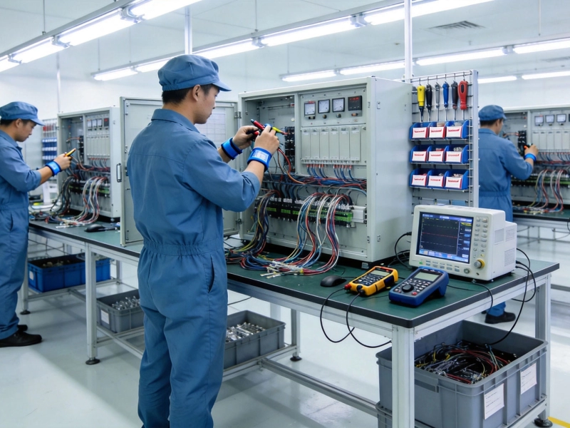
Navigating the Complexities of Box Build AssemblyMay/27/2026
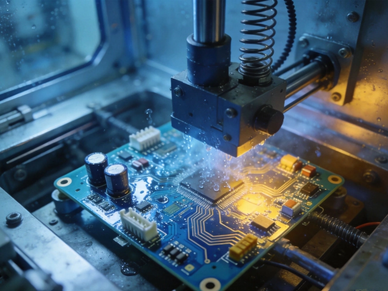
Ensuring Industrial PCB Reliability in Extreme Environmental ConditionsMay/27/2026
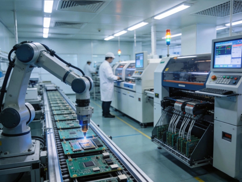
The Complete Guide to Manufacturing Processes and Industry ChallengesMay/27/2026
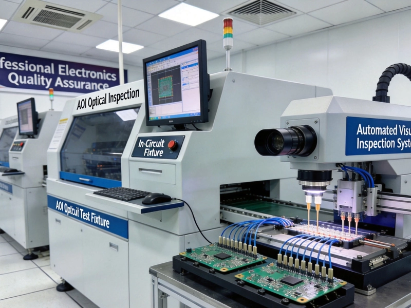
Essential Quality Control Tests for Industrial PCBs- ICT, FCT, and AOIMay/27/2026
Materials, Methods, and Industry Standards ExplainedMay/27/2026
A Comprehensive Guide to High-Tg Materials for Industrial PCBsMay/27/2026
Essential Rules for Industrial PCB DesignMay/27/2026